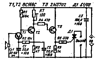
To sound relay, the circuit of which is shown in the figure, as the sensor used in a compact loudspeaker from a pocket radio. The resistance of the voice coil should be around 30-60 Ohm. To better align the sensor resistance with the input device, the first stage is executed according to the scheme with a common base. The second and third stages collected on transistors with different conductivity type (n-p-n and p-n-p).
The device operates as follows. The audio signal received on the input device, is amplified by all three cascades and their role includes the signal applied to the control electrode of the thyristor D1. In its anode circuit, outputs, connects the actuator. For example, the flash, the electromagnetic relay comprising a camera shutter, etc.

The sensitivity of the amplifier can be changed within certain limits, set by the variable resistor R7. Handle this resistor is displayed on the front panel of the device.
To achieve greater clarity of relays in the first two stages it is desirable to use silicon transistors with high gain and low current leakage.
In the first two stages of the device can be applied silicon transistors CTG, in the third cascade - silicon transistor MP 116. In this cascade is possible to use germanium transistor, for example, MP or MP with any letter. As a sensor it is possible to use an electromagnetic earpiece DEM-4.
Literature
- "Practical Wireless", 1972, Jan.
Publication: N. Bolshakov, rf.atnn.ru


