In Amateur practice is often required to control a powerful electrical appliances, for example, heaters, motors, etc. as a Manager the device can act as a timer, the signal receiver remote control an acoustic sensor, etc, to output control signals TTL were or CMOS level. In addition, the control circuit must be galvanically isolated from power. Without such isolation, the operation of electronic the device is dangerous!
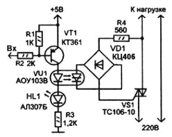
Variant of the control circuit shown in the figure. It uses powerful triac TS-10, which allows to switch loads with maximum current up to 10 A. For galvanic isolation of governors and power circuits used optogenetic, AOB. Triac (symmetrical thyristor) may to work in both half cycle of the AC voltage, i.e., in open he misses both positive and negative half-line voltage.

To disable the load input is necessary to apply a high logic level ("1"). The key VT1 is closed, the current through the led photodirector not flowing, and the triac is closed. To enable the load control circuit is supplied a logical "0". The VT1 transistor opens, the led lit photodirector lights dinistor. A dinistor opens in each half-cycle of voltage. Through the diode bridge VD1 of dinistor connected to the control electrode of the triac VS1. So at the beginning of each half period the triac is also open, and the load receives full voltage. In as VD1, you can use any low-power rectifier bridge, or to make it up of four diodes (CD or similar). Led HL1 (any type) for indicating switching on the load.
To adjust the power output to the load (heater) control unit should to develop the low level pulses, synchronized with the mains voltage. The shift of these pulses relative to the beginning of the half cycle of the mains voltage will cause delay opening optogenetic and, respectively, of the triac. As a result, the load will go only part of the mains voltage.
Author: A. Kashkarov, G. S. Petersburg


