


")

Currently produced many models of wall electronic quartz watch hours with a stepper motor. In them, as a used chip integrated chip - generator/divider external crystal, solid black compound. And well have happened that this electronic unit left down in hours, which served me faithfully for many years.
Required circuits were unable to find them (and it would be difficult for her, chip, still solder in the circuit Board). Had to collect from analogue discrete components (Fig. 1). In particular, the master oscillator to perform on the basis of a CMOS inverter DD1.1, involved in feedback.
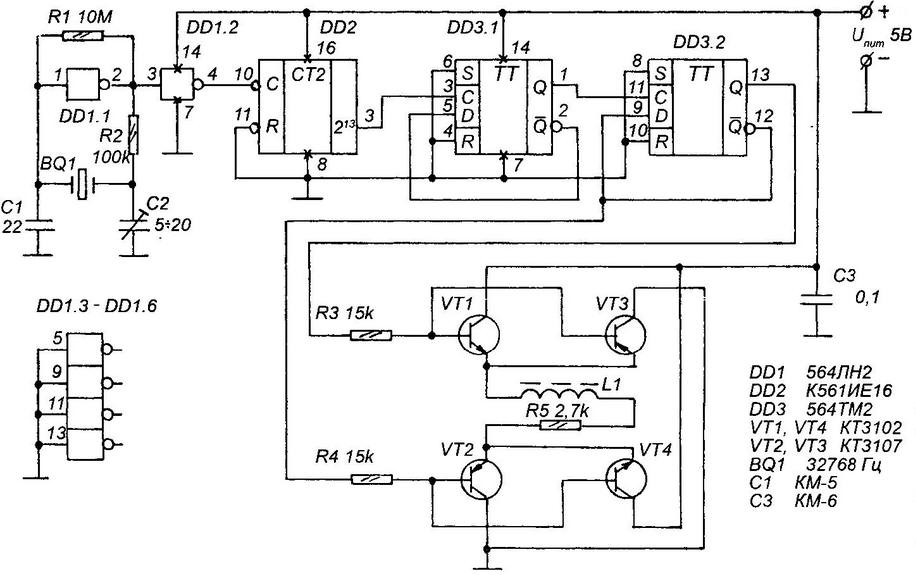
Fig. 1. The schematic for the replacement frameless MS (generator-divider frequency) in a wall-mounted electro-mechanical clock makeshift Assembly discrete using the quartz resonator from broken computer "mouse"
Applied by me quartz resonator BQ 1 has a frequency of 32768 Hz. Through the buffer element DD1.2 the reference signal arrives at the clock input of the counter DD2 CIE with a division ratio of 2:14 = 16384. So, at the output "2:13" 'll have a "welcome dohereby". This signal is next two series-connected frequency divider (each a division ratio of equal to two) based on triggers DD3.1 and DD3.2. Well, in the end, the outputs will be to present direct and inverse signal with a frequency of 0.5 Hz (in other words - one drop per second).
To rotate the rotor of the stepper motor that causes the seconds hand to one position, you must submit in its winding of the first pulse of one polarity, then the other. It then will flow there is a "correct" current: first, from the beginning to the end, and later - from the end to the start winding.
With the implementation of the desired algorithm successfully copes cascade on transistors VT1 - VT4. Direct and inverse signals arrive at the base named semiconductor triode of the trigger output DD3.2 through current limiting resistors R3, R4.
Let at some point on the direct output of the trigger DD3.2 there is a high level, and is inverted to low. This opened the transistors VT1 and VT2 and current flows from the left (the scheme) to the right end of the winding L1 stepper engine.
In the next moment, the direct output is held low, inverse - high; opened the transistors VT4, VT3 and current flows from the right (under the scheme) to the left end of the winding. The direction of the magnetic flux in the magnetic circuit of the motor is reversed, and the gradient, interacting with the magnetic field of the permanent magnet rotor, moves the last one position. Then the process is repeated periodically. Resistor R3 limits the current through the motor winding, reducing the self-induction EMF.
To ensure the self-made device power supply serves as the network adapter. It can also be manufactured in any home workshop, the benefit is a circuit diagram of this adapter is particularly complex not different (Fig. 2). Here are step-down transformer with the voltage on the secondary winding 9 In ("vychodniho" from any old mnogoplanovogo radio), integral stabilizer CREA, switch Yes three capacitors, two of which bolsaescola, electrolytic.
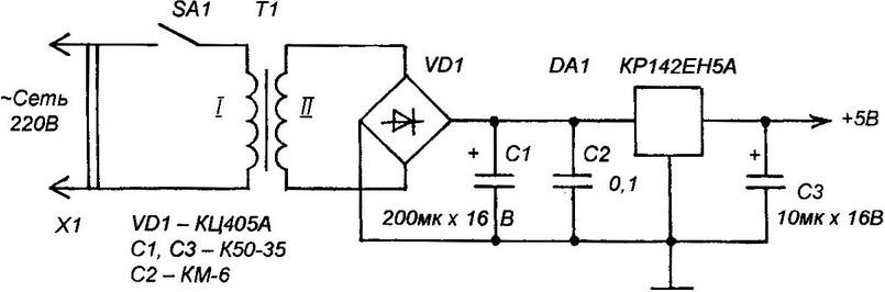
Fig. 2. A circuit diagram of the network adapter for hours
Of course, can be adapted to power any other source able to provide at the output 5-15 VDC. However note that with the increased voltage increases the EMF self-induction induced in the winding of the stepper motor. So, to avoid any complications will have to connect in parallel with the load the two-anode semiconductor Zener XA limiting emissions.
In the device used integrated circuits series 564 (DD1, DD3), it is possible to replace K-m (but would increase the size of the print cost), though as DD2 only recommended a series C and DA1 - CR. Transistors KT3102 (VT1, VT4), CT (VT2, VT3) with any letter the index at the end of the name can if necessary be replaced, accordingly, KT315 and KT361, and rectifier bridge CCA (VD1) similar or even more powerful diode Assembly.
Capacitors, it is desirable to choose from widely available km-5 (C1), km-6 (C3 in Fig. 1 and C2 in Fig. 2), K50-35 (C1, C3 in Fig. 2), and the resistors from equally available C2-22-0125 or their analogs.
A more rigorous approach to the selection of the quartz resonator, which must be tuned to the frequency of 32768 Hz. Such is used, in particular, in push the manipulator "mouse".
Drift is determined by the precision of the frequency setting specifies generator. Alignment here is set by the capacitor C2. This procedure should be performed, if possible, using elektronnoschetnogo frequency.
The installation is carried out on the PCB of bilateral foil PCB or Micarta sizes 60x40x1,5 mm (Fig. 3).
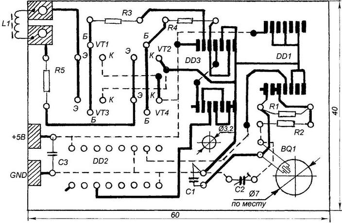
Fig. 3. A printed circuit Board, a homemade device
Author: V. Vasilenko