


")

The device can be used as a useful additional attachment to any stationary audio amplifier and allows in the absence of the signal on the output load (the speakers in the columns) during the time interval more than 4 minutes, automatically switch off the radio from the mains 220 V, if you forget to do it before.
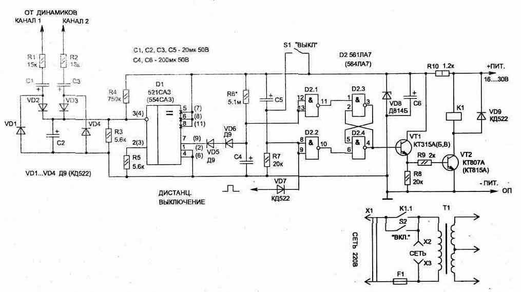
Fig. 1.9 (click to enlarge)
Electric circuit device shown in Fig. 1.9, and contains scarce and expensive parts. The signal output from the speakers stereo amplifier (if amplifier, single channel, connecting only one input) through the coupling capacitors C1 and NW is supplied to the rectifier from diodes VD4 VD1…(they can be replaced with a single diode array KDA). In the presence of rectified the voltage on the capacitor C2, the comparator D1 is opened and its output (the output 7) through the diode short-circuits the capacitor C4. In the absence of a sound signal the comparator is not working and C4 through the resistor R6 is charged up to voltage 7.5 In for 4 to 5 minutes (time can be increased or reduced by changing the values of C4 and R6).
As soon as the voltage on the capacitor exceeds the level the switching threshold of the chip D2.1, at its output (pin 11) will be zero the voltage that will switch the trigger on the elements of the chip D2.3, D2.4 (will be zero voltage on pin 4). When the relay K1 is turned off and their contacts K1.1 disconnect the power circuit of the amplifier, as well as other radio equipment, connected to the jacks x2, XS.
For manual-on (82) and off (S1) radio equipment uses two independent buttons without fixation, any type, with contacts, designed to operate at a voltage of 220 V.
The circuit device includes remote turn off the radio. For this purpose, the input D2.2 through the diode VD7 served positive pulse amplitude of 7 V, for example, from the temporary timer.
Powered circuit from the amplifier positive voltage 16…30 V.
When button S2 is switched on, the transformer of the amplifier, since the secondary winding of which immediately after the rectifier is supplied with voltage on the scheme. Relay K1 is activated and its contacts K1.1 locks the button S2,
Relay K1 is used type DE-PD, but the fit and many others, for example RAN HR.500.000. While choosing, you must consider permissible operating voltage contact switching current, as well as working the voltage winding: it will be determined by the value of the voltage that is in the amplifier.
Used resistors and capacitors can be any type, comparator D1 can be replaced by SS, but it will change the numbering conclusions it is in the diagram shown in parentheses.
Publication: www.cxem.net