In the household often face with a situation where appliances should work in periodic mode. Without this, for example, the heater may overheat serve the object and the fan to create an unpleasant sensation of draught. Modern electronics make it easy to solve the above-mentioned the problem.
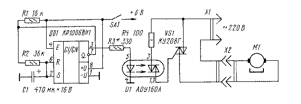
The electrical circuit of the machine such appointment shown in the figure. It includes working in multivibrator mode timer CRUE - DD1 [1], semesterly OPTRON AOA - U1 [2] and power switch on samestore VS1. Function controlled loading performs the motor M1 of the electric fan. Capacitor C1 is connected to resistors forms frameshadow chain, determining the duration of the on and off status of the load.

This device works as follows. When power is applied to the chip DD1 starts charging the capacitor C1 and the result on the output 3DD1 there is a voltage close to the voltage power. At the end of the charge inside the chip C1 DD1 opens transistor, connecting her seventh and first conclusions, resulting the capacitor C1 discharges through the resistor R2. After this cycle of the device is repeated. The voltage close to the supply voltage, periodically appearing on the output circuits DD1, through current limiting resistor R3 is supplied to the led in the control circuits optocoupler U1. Under the influence of the emitted light energy which is part of the optocouplers semester goes into the conducting state, and consequently opening of the power triac VS1 includes a motor M1.
The most important function of the optocoupler designed for the voltage between the input and output circuit 1500 In - reliable electrical isolation of the input and output circuits. Until such electronic components the goal of dividing circuits solved using cumbersome electromagnetic relays. SCR VS1 with two-way conductivity opens with the beginning of each half period of the mains voltage, while signal is output circuits DD1 and the led of the optocoupler. Power driven load is determined by the allowable current value semistar VS1. The chip itself DD1 and the led of the optocoupler when the voltage power 6 In current consumption is about 8...12 mA, so the power can even be used galvanic cells LR6 (foreign standard AA).
In the machine used resistors MLT-0.125 (R1-R3) and MLT-0.5 (R4), capacitor - K52-1B. As the switch SA1 is used microtubles MT.
When specified on the circuit component values timing chain period and the off load is respectively 0.3 and 0.2 min. by Choosing different ratios of the values can to change and the cycle of operation of the device. The resistance of the resistor R3 should be selected so that when the fresh battery, the current through the led OPTRON was 10...12 mA (recall that the maximum allowable current is 40 mA).
During installation it is important to ensure that to the output circuit of the optocoupler and power semester were safely isolated from circuits associated with the chip DD1, and from the walls of the case (if it is made of of metal). Depending on the power connected to the load device, power triac may need a heat sink. In this case, hard case should be equipped with ventilation holes. To join a machine appliance-load (in our case the engine) on the case is attached standard receptacle X26 which a flexible cord with plug X1 included in the network.
Literature
- Petsiukh E., Casares A. Integral timer CREW. Radio, 1986, №7, p. 57
- Yushin A. Optocouplers series AO. Radio, 1997, No. 10, p. 64
Publication: N. Bolshakov, rf.atnn.ru


