The era of "mobilization" and computerization surrounds us all kinds of network adapters required for charging mobile devices that supply numerous printers, scanners, toys, and other designs. These adapters can be with the voltage regulator, and without (contain only step-down transformer, rectifier and oxide the filter capacitor). Unpleasant feature of the latter is that they, as a rule, do not contain nodes of the protection against short circuit or overload (even an ordinary fuse), which often leads to their deterioration, especially annoying when damaged mains transformer.
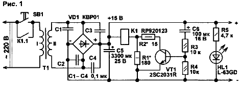
In Fig.1 shows a diagram of a simple network adapter, supplemented relay host protection against short circuits.

To the adapter received voltage power, you need a short press on the button SB1 (without fixation). Then on the output of the rectifier VD1 you receive a constant voltage. At the initial moment the capacitor C6 is discharged, and the VT1 transistor opens its charging current. Through open the transistor and current limiting resistor R2 to the relay coil comes sufficient to enable the voltage, the contacts K1.1 are closed and block button. If we now drop the SB1. the PSU stays on. After 2 to 4... with the capacitor C6 is charged, VT1 is closed, but because through R1 and the winding relay flows sufficient to hold the relay current, the device still included. If a load short circuit occurs, the relay coil abastecida, the relay contacts will open, and the PSU shuts down.
The node protection is convenient to use both in stable and in unregulated power supplies with an output voltage of at least V. 9 Especially it is convenient to embed in a simple charger for car batteries. To the node protection worked reliably, a capacitor C5 must have the minimum capacity of 1000 UF.
If a little to complicate the scheme, the described device will be able to protect network adapters and low output voltage. As an example in Fig. 2 typical diagram of a simple power supply with fixed output voltage 3.3 V. which can be used for stationary power different mobile devices, children's toys, etc.

If a short circuit or severe overload developed by the transformer and the rectifier may not be sufficient to engage the built-in stabilizer DA1 system protect the device against overload. In this case, through rectifier VD1 and the transformer can occur invalid for them current. In addition, not all the stabilizers are integrated trigger system protection. The majority of linear integral stabilizers simply limit flowing current through them to secure for themselves.
The second feature of the scheme is that the relay is activated higher unstabilized voltage taken from the output of the rectifier. To hold the relay is a voltage of 3 V from the output of the stabilizer. In case of short circuit in the load the output voltage of the stabilizer is equal to zero, the winding the relay is de-energized, its contacts K1.1 opens, and the power supply is disconnected from the network.
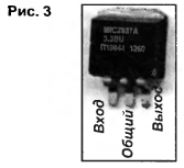
The relay in the device - type RP920123 from faulty UPS. These relays have a coil resistance of about 185 Ohms, the voltage is not less than 8.5 V. and the voltage drop is not more than 2.5 V. Dial-up contacts alternating current in the circuit of 220 V must not exceed 8 A. the Diode VD1 - A81-004-37 with a voltage saturation of not more than 250 mV at a current of 40 mA. You can replace outdated germanium, for example, the D7 series, D311. Transistor 2SC2031R can be replaced any of the series SS8050, 2SD261. CT, KT815. CT. Instead 2SA935 can apply SS8550, CT, CT. CT. Appearance and Pinout of the chip MIC2937A shown in Fig. 3.

If required, it is mounted on the heat sink. Similar sites protection can be embedded in other, diverse sources of power. Besides protection the transformer and diodes overload, they will also prevent spontaneous switching adapters or power supplies after outage power supply voltage, which in many cases is very useful.
When upgrading the cheap adapters that have an unreliable "Chinese" transformer, to reduce the likelihood of sudden burnout its primary winding, in series with this winding to include current limiting resistor required power resistance approximately equal to the resistance the primary winding. It is desirable that the resistor was a non-combustible or burst type, for example, P1-7.
Author: A. Butov, S. CORBA Yaroslavl region


