


")

The device is designed to prevent overloading and faults in the radio equipment due to voltage deviation power for admittance. It will be particularly useful in the country or in the village, where frequent significant voltage fluctuations in the network. Often used in unstable network ferromagnetic the stabilizers have a narrow range of stabilization and in large fluctuations in voltage (upwards) just fail. For some radio equipment dangerous not only high but also low voltage network.
To control the network by the measuring device, each before starting radio devices, it is inconvenient and inefficient, since the deviation may occur in the process. But this task can take over automatically the control device, through which equipment and feeds.
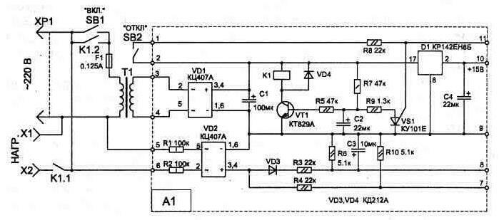
Fig. 1.34
Fig. 1.35
When you initially turn on the device (the button SB1) it for one second checks the level of the mains voltage at finding his admission 170…260 V, and the presence of noise. In the case of voltage deviation the permit scheme will not allow you to turn on the radio.
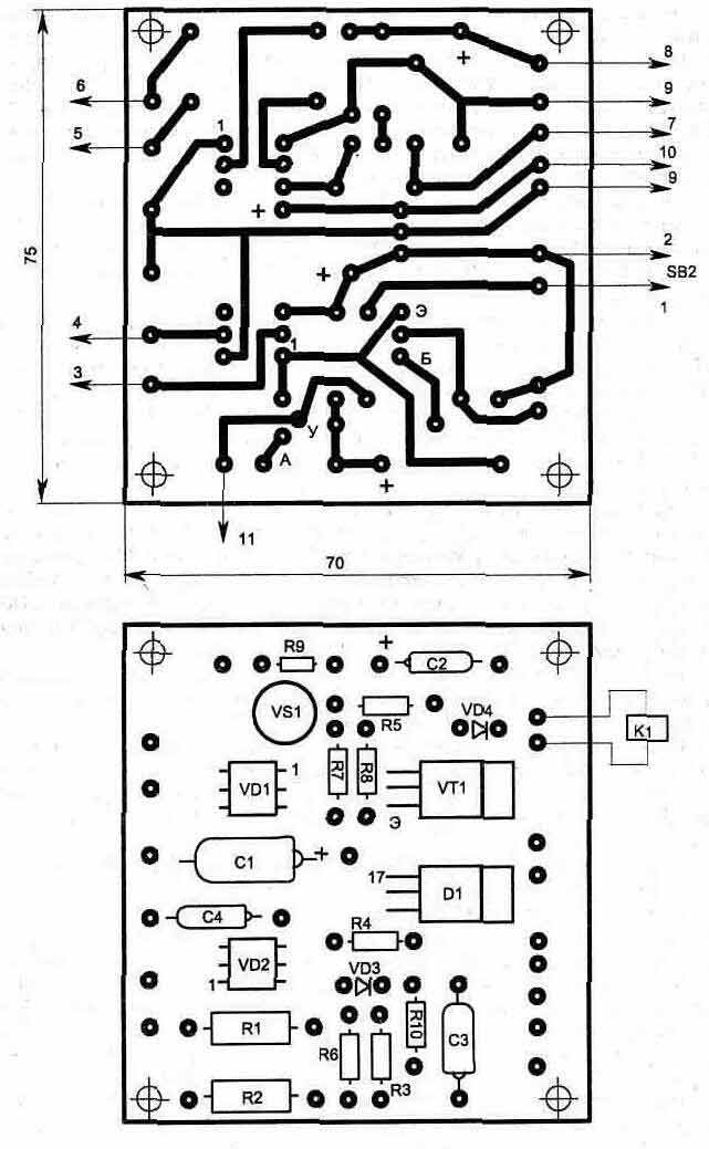
Fig. 1.36. A printed circuit Board, for node A1
In operation, the protective device scheme produces continuous monitoring of network status, and when the output voltage tolerance is 190 245… In starts to work the alarm, warning that better off the radio equipment. In this case, the illumination of the led indicator, you can define type of voltage deviation in "+" (increase) or "-" (decrease). In the case of the dangerous inconsistencies in the mains voltage (at the output of the tolerance 170 260… B) the radio equipment connected to the sockets X1, x2, will turn off automatically.
Electric circuit device shown in Fig. 1.34 and 1.35 and consists of a four-level comparator on the elements of the chip D2, a sound generator on the elements of D3.1…D3.3, node of the switching transistor and the relay K1, and a power supply unit with voltage regulator on a chip D1.
The threshold of the Comparators is set when you configure the resistors marked on the diagram with an asterisk "*". Their the values indicated in the diagram roughly. Device setup is done with the help of LATRI, changing the voltage on the plug HR. In this case resistor R15 set the threshold is exceeded 245 V (output D2/8 will log. "1"), a resistor R14 to the voltage reduction below 170 In (output D2/8 log. "0"). To configure convenient to use the large size of the adjusting resistors.
Schema customization is better to start with the validator node, shown in Fig. 1.34. When you press the on button (SB1), the relay K1 is activated with a delay of about 1 second and the contacts K1.2 blocks button. The delay time the relay depends on the value of the capacitor C2 and resistor R7. Off relay K1 may be made by the off button (SB2) or from the scheme of automation, when the output of the chip D3/11 will have the momentum or the log. "1" (when entering voltage tolerance).
In Fig. 1.36 shows a printed circuit Board, for the section of the scheme (A1), highlighted by the dotted line. The rest of the circuits are made universal breadboard surround installation.
The circuit has capacitors C1…C4 type K52-16 63; C5, C6 - K10-17. Resistors and diodes you can use any similar. Transformer T1 better use of unified series CCI. It needs to provide in the secondary winding voltage 22…24 V and a current not less than 60 mA.
The relay K1 is applied type RAS (passport 4.590.201), but will fit many others, with an operating voltage of 24 V.
The automatic protection device can be simplified if we abandon the sound and light alarm voltage deviation. In this case, a control circuit voltage in Fig. 1.35 model shown in Fig. 1.37 . It consists of transistors, operating in the micro. In normal condition trimmer resistors R12 and R15 mounted on collectors VT2 and VT3 log. "On" and the log. "1", respectively. In this case, the transistors VT4 and VT5 locked and the resistor R19 is no voltage (when work VS1).
Changing the supply voltage with the help of LATRI, resistor R12 set the threshold circuits when the voltage is below 170, and resistor R15 - in excess of 260 V.
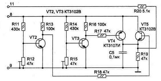
Fig. 1.37
When using the second version of the schema is simplified and block A1. In this case, the stabilizer D1 is not needed, and if the transformer T1 a spare winding for voltage 6…12 V, it can be connected to circuits 5 and 6 (instead of resistors R1-R3 to set the jumpers, R4 and R10 to exclude from the diagram).
Publication: www.cxem.net