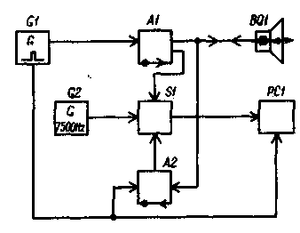
Structural diagram for explaining the device and the operation of the sounder is shown in Fig. 1.
Clock generator G1 controls the interaction between device units and provides its operation in automatic mode. It generates a short (0.1 s) rectangular pulses of positive polarity are repeated every 10 s. His front these pulses set the digital counter PC1 in the zero state and close the A2 receiver, making it insensitive to signals at the transmitter. Decay clock pulse triggers the transmitter A1 and the emitter-sensor BQ 1 emits in the direction of the bottom short (40 MS) of the ultrasonic probing pulse. At the same time opens the electronic key S1, and oscillations of standard frequency 7500 Hz from the generator G2 is received in digital counter PC1.

Fig.1
Upon completion of the transmitter receiver A2 is opened and becomes normal sensitivity. Echo signal reflected from the bottom is the sensor BQ 1 and after amplification in the receiver closes the key S1. The measurement is complete, and indicators counter PC1 highlight the measured depth. The next clock pulse again switches the counter PC1 in the zero state, and the process repeats.
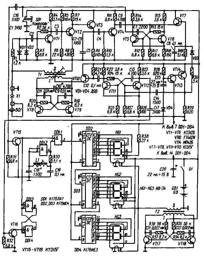
Schematic diagram of the sounder to measure the depth to 59.9 m depicted in Fig. 2. His transmitter is a push-pull oscillator transistors VT8, VT9 with a tuned to the operating frequency of the transformer T1. Required for self-excitation of the generator positive feedback create a chain R19C9 and R20C11. The generator produces pulses with a duration of 40 μs with a radio-frequency filling. The transmitter controls the modulator consisting of a single vibrator on the transistor VT11, VT12, forming a modulating pulse with a duration of 40 μs, and the amplifier transistor VT10. The modulator operates in a standby mode, a triggering clock pulses through the capacitor C14.

Fig.2
The sounder receiver is built on a forward gain. Transistors VT1, VT2 increase passed by the emitter-sensor BQ 1 echo signal, the transistor VT3 is used and the amplitude detector, the transistor VT4 enhances proyektirovanii signal. Transistors VT5, VT6 assembled a single-shot, ensuring the constancy of the parameters of the output pulses and the sensitivity threshold of the receiver. From pulse transmitter receiver protect diode limiter (VD1, VD2) and the resistor R1.
In the receiver used forced off the single-shot receiver using transistor VT7. At its base through a diode VD3 receives a positive clock pulse and charges the capacitor C8. Opening, the transistor VT7 connects the base of transistor VT5 of single-shot receiver with positive feed wire, thus preventing the possibility of triggering from the incoming pulses. At the end of the clock pulse, the capacitor C8 is discharged through a resistor R18, transistor VT7 is gradually closed, and a single-shot receiver acquires a normal sensitivity. The digital part of the sounder collected on chips DD1-DD4. It includes the key on the element DD1.1, driven RS-trigger on the elements DD1.3, DD1.4. The impetus to start counting is supplied to the trigger from the modulator of the transmitter using transistor VT16, graduating from the receiver output through the transistor VT15.
A pulse generator with an exemplary repetition frequency (7500 Hz) collected on the element DD1.2. From resistor R33 and the coil L1 is composed of a negative feedback circuit that outputs an element on the linear portion of the characteristic. This creates conditions for self-excitation at a frequency determined by the circuit parameters L1C18. Exactly to the set frequency generator configures the podstroechnik coil.
The standard frequency signal through the switch enters the three digit counter DD2-DD4. In normal conditions it sets the front of the clock pulse supplied through the diode VD4 to the inputs R of chips.
Clock generator for controlling the operation of an echo sounder is built on transistors of different structure VT13, VT14. The pulse repetition rate defined time constant circuit R28C15.
The cathodes of indicators HG1-HG3 powers generator transistors VT17, VT18 [2].
Button SB1 ("Control") is used to check the operation of the device. When pressed on the key VT15 enters a closing impulse and sounder indicators reveal a random number. After some time, the clock pulse toggles the meter, and indicators should highlight the number 888, which indicates the health of the sounder.
The sounder is mounted in a box made from high impact polystyrene. Most parts are placed on three printed circuit boards of foiled fiberglass 1.5 mm thick. On one of them (Fig. 3) mounted transmitter, on the other (Fig. 4) receiver, the third (Fig. 5 - the digital part of the sounder. Board mounted on a duralumin plate dimensions H mm, embedded in the lid of the box. At the plate and the lid and drilled holes for the power switch Q1 (MT-1), the button SB1 (KM1-1) and the socket BP-74-f coaxial connector XI and cut out the window for digital indicators.
In the sonar used resistors MLT, capacitors KLS, CTC and K53-1. Transistors CTV and GTI can be replaced by any other transistors these series, MP42B - MP, CTG-CTV. Chip series C interchangeable corresponding series C, chips instead of KIT (DD4) can be used CIE. If the sounder will be used at a depth of 10 m, DD4 counter and indicator HG3 can be omitted.
Winding of the transformer T1 is wound wire PELSHO 0.15 per frame diameter 8mm with fer-riculum (N) podstroechnik diameter of 6 mm. the winding Length of 20 mm. Winding of I contains 80 turns with a branch of the middle, winding II - 160 turns. Transformer T2 is made on a ferrite (NM) ring size CHJ,5. The winding of I contains 2 180 turns of wire sew-2, 0,12, winding 11-16 turns of wire sew-2, 0.39 in. Coil L1 (1500 turns of wire sew-2 0,07) is wound between the cheeks on the frame 6 mm in diameter made of organic glass. The diameter of the cheeks - 15, the distance between them is 9 mm. Podstroechnik - armor from the magnetic MO-1A from carbonyl iron.
Ultrasonic emitter-sensor sounder produce on the basis of a circular plate with a diameter of 40 and a thickness of 10 mm made of barium titanate. Its silver-plated planes alloy wood too thin (0.2 mm diameter) conductors-conclusions. The sensor is assembled in an aluminum Cup from the oxide capacitor with a diameter of 45...50 mm (height - 23...25 mm - specify when assembling). In the center of the bottom of the Cup drill the hole for the pipe through which will include a coaxial cable (RK-75-4-16, length 1...2.5 m) connecting the sensor with sounder. The sensor plate is glued with glue 88-N to the disk of soft foam rubber 10 mm thick.
When mounting the cable are soldered to the socket, center conductor to the output electrode of the sensor is glued to the rubber disk, the output of the other cover to the braided cable. After that, the disc plate is slid into the glass, passing the cable into the fitting hole, and fix the fitting nut. The surface of Titus-natuloy plates must be deepened in a glass 2 mm below its edge. The glass is fixed vertically and fill to the edge of the epoxy. After hardening of the resin surface of the sensor are polished with fine sandpaper to produce a smooth plane. To the free end of the cable solder mating connector XI.
To establish sounder necessary oscilloscope, digital frequency counter and a power supply voltage of 9 V. turn the power on, check the efficiency of the counting device: if it is fine, the indicators should highlight the number of 88.8. When you press the SB1 should appear a random number, which with the arrival of the next clock pulse should again be replaced by a number of 88.8.
Next, adjust the transmitter. To connect the sounder transducer and an oscilloscope operating in the standby mode sweep,- to the winding 11 of the transformer T1. On the oscilloscope screen with the arrival of each clock pulse must receive an impulse radio-frequency filling. The podstroechnik of the transformer T1 (if necessary, choose a capacitor C10) achieve the maximum amplitude of the pulse, which must be not less than 70 V.
The next stage is the establishment of pulse generator model frequency. For this frequency through the resistor a resistance of 5.1 kω must be connected to the pin 4 of the chip DD1. The frequency of 7500 Hz generator set by podstroechnik coil L1. If podstroechnik occupies a position far from the average, choose a capacitor C18.
The receiver (and modulator) are best set by echo signals, as described in [I]. For this purpose, the sensor is attached to the rubber strap to the end wall of the plastic box the size HH mm (with the aim of eliminating the air gap between the sensor and the wall lubricate it with petroleum jelly). Then the box is filled with water, fed from the receiver diode VD3 and must be connected to the output of the receiver to the oscilloscope. The criterion for the correct settings of the receiver, the modulator of the transmitter, and the quality of the ultrasonic sensor is observable on the screen of the echo signals arising from multiple reflections of the ultrasonic pulse from the end wall of the box. To increase the visible number of pulses of the selected resistors R2 and R7 in the receiver, the capacitor C13 in the transmitter modulator and change the position of podstroechnik of the transformer T1.
To adjust device-on delay receiver solder the diode VD3, replace the resistor R18 variables (resistance of 10 ohms) and use it to achieve the disappearance of the first two echoes on the oscilloscope screen. By measuring the resistance of the entered part of the variable resistor, it is replaced with a constant in the same resistance. After you configure the number of echoes on the oscilloscope screen must be at least 20.
To measure the depth of the reservoir, the sensor is best mounted on the float so that its lower portion was immersed in water at 10 to 20 mm. it is Possible to attach the sensor to a pole, with which they are immersed in water briefly, at the time of measurement depth. When using sonar in flat-bottomed aluminum boat for measuring small depths (up to 2 m) sensor can be glued to the bottom inside the boat.
In conclusion, it should be noted that on Sunny days the brightness of digital displays may not be sufficient. To improve it by replacing the battery "Corundum" ("Crown") power source with slightly higher voltage, for example, a battery composed of eight batteries D-0,25 (no changes to the scheme and design of this device does not require).
Literature
Authors: V. Voitsekhovich, V. Fedorov; Publication: N. Bolshakov, rf.atnn.ru


