


")

We offer our readers the sounder can be used to determine bottom topography and measure the depth of water bodies, search for sunken objects, as well as finding the most promising places for fishing. The device is very simple in adjustment, easy to operate and does not require calibration.
The sounder is designed to measure the depth of the reservoirs at the four limits: up to 2.5; 5; 12.5 and 25 m. the Minimum measured depth of 0.3 m. the Accuracy is not exceed 4% of the upper value limit on any measure. The device provides a temporary automatic gain control), allowing to change its amplification factor during each measurement cycle from minimum to maximum and, thus, improves the immunity. The need for control due to the fact that any radiation of acoustic energy into the water leads to intense reverb, i.e. multiple reflection the ultrasonic signal from the bottom and the surface of the water. Therefore, at small depths may be a false alarm host reception of echo signals. Thanks to TVG significantly improves the function of the device for measuring the depth in the range of 0,3…3 M.
As an indicator in sonar, we use linear depth scale, consisting 26 LEDs, which can be displayed up to four reflected the limits measurements. The period of updating the information on the indicator is about 0.1 s, which makes it easy to track the topography of the bottom in the movement. Increases the noise immunity of the sounder pulse software filter that protects it from random noise. When the filter indicator displays only those signals the values of which for the period of measurement (0.1) has not changed more than 1/50 of the selected limit of measurement. Powered device from six elements A316, and its operability is maintained at a voltage reduction to 6 V. the current consumption is in the range 7…8 mA (excluding current through the LEDs at 10 mA per illuminated led).
The sounder provides the possibility of rapid switching of the limit of measurement, the number of displayed reflections, and adjust the effectiveness of TVG. Pulse the filter can optionally be disabled. Values of all parameters can saved in the memory into power-down mode ("SLEEP"). In this mode consumption current is about 70 mA, which is almost never affects lifetime of batteries.
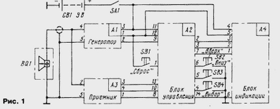
The sounder consists of four functionally complete units: the generator probe pulses, a receiver, a control unit and a display unit (Fig. 1).
Schematic diagram of the generator probe pulses is shown in Fig. 2.
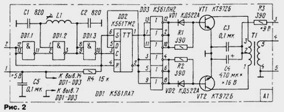
Specifies the pulse generator assembled on a chip DD1. It generates pulses frequency of 600 kHz, which is then divided by two by a trigger on the chip DD2. On chip DD3 assembled buffer amp, a matching trigger with amplifier power made push-pull circuit composite transistors VT1, VT2 and the transformer T1. With its secondary winding electric oscillations of a frequency of 300 kHz received for a piezoceramic emitter - sensor BQ 1 and in the form ultrasonic parcels are emitted into the environment. The operation of the generator allowed in the presence of a logical zero level on the terminals 12, 13 of the chip DD1 and 4, 6 chip DD2.
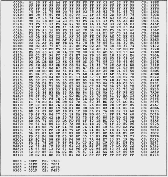
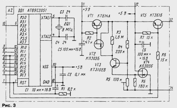
An enable pulse with a duration of 50 μs comes to the generator at the beginning of each measurement cycle with the control device (Fig. 3). All signals necessary for operation of the device, form a single-chip microcontroller DD1 (ATS). Machine codes of the control program in the internal program memory the microcontroller shown in the table.
(click to enlarge)
The checksum calculated by the algorithm "Radio-86RK. Transistors VT1-VT4 made stabilizer for voltage of 5 V. Its characteristic features - the small quiescent current of 25 µa and small the voltage drop across the regulating transistor is less than 1 V. the Transistor VT5 remove power from the receiver in "SLEEP" mode, which, as noted above, reduces current consumption.
Reflected from the bottom of the pulse signal in the interval between transmissions the emitter-sensor and is input to the receiver (Fig. 4), increasing three-stage resonant amplifier transistors VT1, VT2, VT4-VT7, after what is detected by diodes VD4, VD5. The Schmitt trigger transistors VT8, VT9 generates standard logic levels. Diodes VD1, VD2 protect the receiver input from overload. VT3 transistor performs the functions of control control, changing in wide limits the gain of the cascade transistors VT1, VT2.
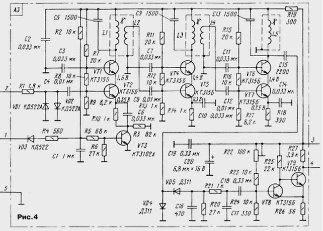
The shape of the control voltage on the capacitor C1 at maximum efficiency TVG is shown in Fig. 5.
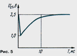
The normal charging time of the capacitor is determined the time constant circuit R2C1, and the lower the level of stress - resistance resistor R4 and duration of the discharge pulse control device, which can vary from 0 to 1.25 MS. Changes accordingly the effectiveness of the control that allows you to quickly adjust the sensitivity sonar for specific conditions. With the collector formed VT9 the reflected pulse is supplied to the output P3.2 microcontroller DD1 device management for further processing.
Diagram of node display shown in Fig. 6. It is a 32-bit the shift register four chips DD1-DD4 (CIR) with emitter repeaters output.
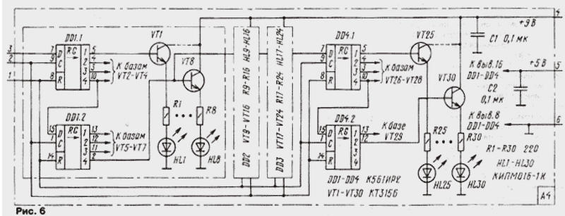
The resistors R1-R30 set the current to 10 mA through the LEDs HL1-HL30. In this current indicator is visible in any weather. The last two discharge IC DD4 not used. LEDs HL1-HL26 form a major the scale indicator, and HL27-HL30 indicate the limit of measurement, the number of displayed reflections and pulse noise filter. Their placement on the front the panel shown in Fig. 7.
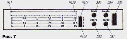
Button SB1-SB4 (see Fig. 1) is also displayed on the front panel, with their help quickly change modes of operation of the sounder.
The design of the ultrasonic transducer of the sensor is explained in figure. 8. He is a circular plate 1 diameter 31 6 mm piezoelectric PZT-19 the resonant frequency of 300 kHz. To the silver-plated surfaces of the plate alloy wood solder three wire cut MGTF-0,1. Space ration should be at the edge plate and positioned on its circumference evenly.
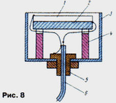
The sensor is assembled in an aluminum Cup 3 from the oxide capacitor diameter about 40 and a length of 30 to 40 mm. In the center of the bottom of the glass drill hole fitting 5, through which is flexible coaxial cable 6 length 1…2.5 m, connecting the sensor with sounder. The sensor plate is bonded to the disk of soft microporous rubber 2 thickness of 5…10 mm and a diameter equal to the diameter of the plate. Soldered to the piezoelectric element findings are collected into a bundle so that its axis coincides with axis of the piezoelectric element.
When mounting the cable are soldered to the socket, center conductor - to conclusions the plates of the sensor is glued to the rubber disk, the findings of the other cover the braided cable. Technological stand 4 fix the position of the plates in a way that its surface was indented into the glass 2 mm below its edge. The glass is fixed vertically and fill to the edge of the epoxy. When this need to ensure that there were no air bubbles.
In the sonar widely used common parts. Coil L1 of the generator wound on the frame with a diameter of 5 mm with podstroechnik NN. It contains 110 of turns of wire sew 0,12. Transformer T1 is made on the annular magnetic core CHH mm ferrite MNM. The primary winding is wound in two wires and contains h, secondary - 150 turns of wire sew 0,21. Between the windings laid a layer of varnished cloth. Receiver coil wound on the frames from the inverter circuits (465 kHz) pocket receivers. Contour coil L1, L3, L5 contain 90 and the coil links L2 and L4: 10 turns of wire sew 0,12. You can use ready the contours of the inverter from handheld receivers 70 - 80-ies, choosing capacitors for obtain the resonant frequency of 300 kHz.
Capacitors C1, C2 generator and C5, C9, C13 receiver should have a small TKE (not worse M75), suitable, for example, capacitors KSO-G, km-5, km-6. Capacitor C1 receiver - K73-17. The LEDs HL1-HL30 red glow rectangular shape, for example IPMB-1K. Field-effect transistors VT2, VT4 stabilizer (see Fig. 3) - K, K with any letter index, but with pinch-off voltage of not more than 2 V. the Microcontroller ATS can be replaced ATS or S. It is necessary to consider differences in the numbering of conclusions. Domestic analogue S is CRUE. The use of microcontroller CRUE with external program memory is impractical, as it significantly will increase power consumption and dimensions of the device. Get acquainted with the internal structure and instruction set of the microcontroller in [1]. Other details special requirements.
All blocks of the sounder can be mounted on one or more printed boards, the size and configuration of which is determined by the size available in the presence of the enclosure and used parts. The receiver is desirable to mount on a separate Board "in line" and place in the housing as far as possible from of the control device. To reduce the heat direct sunlight corps should be light.
The establishment of sounder begin with installation at the output of the stabilizer device the control voltage +5 V. this is done by using a resistor R5. In this case chip DD1 should be removed from the sockets. After the installation of the microcontroller place to verify the operability of the control device and node display.
After power-on indicator should illuminate one of the LEDs additional scales (HL27-HL30) indicating the limit of measurement. Clicking on button SB2 "Up" and SB3 "Down", you can switch the measurement range. A single press of the button SB4 "Select" switches the device into the setup mode the number of displayed reflections. Similarly, pressing SB2 and SB3 can to change this number from 1 to 4, which is indicated by a flashing led on the scale limits. The next time you press the button SB4 mode of installation degree TVG, which is also regulated by buttons SB2 or SB3 and is indicated by a flashing the led on the main scale of depth. By clicking on the button SB4 again, can to disable or enable pulse noise filter also using the buttons SB2 and SB3 respectively. Finally, the fourth button SB4 returns the instrument to the main mode of the switching limits.
In all modes on the depth indicator will be displayed reflected pulses (if any), and if the depth is greater than the set limit, basically the mode will flash the latest led depth indicator - HL26. For memorizing the selected modes, press and hold the button for SB4 approximately 2 s. then the indicator turns off and the device enters the sleep mode low-power "SLEEP". Exit this mode by pressing the button SB1 "Reset". However, if you press SB1 in operation, will happen reset all settings to their original, recorded in the ROM.
Making sure work properly the microcontroller, proceed to the adjustment of the generator probe pulses. First, you must use the oscilloscope to verify the presence of a negative pulse of 50 μs with a period of 100 MS at pin P1.0 of the microcontroller. Then the oscilloscope connected in parallel the emitter-sensor and observe the form of the probing pulses. Their amplitude can reach 100 V. Lowering the transducer into a vessel with water depth not less than 40 cm, can be observed and reflected pulses. Rotating podstroechnik coil L1, you should configure the generator to the resonant frequency of the emitter, focusing on the maximum amplitude of the reflected pulses. The amplitude of the first of them may to reach 5…10 V. the amplitude of the same probe pulse is almost independent frequency.
The establishment of the receiver starts with the set-up transistors on a permanent current in accordance with the flow chart.
This operation must be performed when removed from the socket the microcontroller. When need modes you can adjust the resistor dividers in base the chain of transistors.
Then you need to set the resonant circuits on the generator frequency. For this in the air the radiator is located at a distance of 15…20 cm from any obstacles and with the help of the oscilloscope setting up the contours for the maximum amplitude of the pulses at the collectors VT1, VT4, VT6. In this case be aware that the radiation pattern of the emitter in the air very narrow.
As settings should improve the effectiveness of control or increase the distance to the obstacle to avoid clipping. Finally the contours adjust, by observing the signal after the detector to the junction point of elements R21, C17, C18. Finally, by connecting an oscilloscope to the collector of the transistor VT9, a trimming resistor R22 set the threshold Schmitt trigger, achieving maximum sensitivity and no false positives. The receiver sensitivity is about 15 mV.
Work TVG control, observing the shape of the voltage on the capacitor C1 receiver. If necessary it can be changed by selection of the values of elements R4 and C1.
With the theory and practice of measuring the depth of water bodies ultrasonic sonar can be found in the following literature [2-7].
Literature
Author: I. Khlopin, Dolgoprudny, Moscow region