


")

Even the most timid attempts to shift to electronic equipment, some functions that people used to think "", and, respectively, irreplaceable, worried, cautious attitude. Last but not least this applies to recreational fisheries - one of the most conservative forms of human passions.
Although it is difficult to imagine a more interesting occupation for the Amateur constructor. Starting from the performances occur here, from "algorithmic intuition, to test invented. And not in the virtual space, where we recently highly name, and in the most that neither is this: under the sky, among forests and meadows, with a splash of water and fish without a bar code.
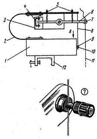
Fig. 1. Kinematic scheme of rods machine
Kinematic diagram of the device, intended for automatically hooking fish in difficult conditions of fishing shows in Fig.1. Here: 1 - body, which houses all electronic and mechanical "stuffing" machine; 2 - flat spring, the main mover of the machine; b - spring rocker with clip 7 line 11, forming with the bracket 4 mounted on the insulating the plate 3, the contact pair; 8 - thrust with earring hook 9; 10 - reducer shaft threaded MOH at the end; 12 - clamp mounting machine on Board or feed the transom of the boat.
In the cocked position the machine is held by a coupling shaft 10 of the gearbox with earring 9. The engine can instantly, within a few revolutions of the rotor, disconnect the hitch. And here is at what point it will happen - will decide the electronics of the machine.
The algorithm of its work is simple. The first electrical sensor signal that occurs at the moment of contact of the rocker 6 of the bracket 4, puts the machine in the active state: the countdown begins and these are still unclear on the origin of taps. If the total number and interference, and bites - in this case, the active state of the machine (its duration set) is less than some number N (also asked), the machine again takes the initial state is the idle state. If this number is reached, then turn on the motor and the cutting.
This algorithm is implemented electronic "stuffing" machine, schematic diagram of which is shown in Fig. 2.
Here: SF1 - pin a pair of yoke-bracket - sensor system; SF2 - pin pair "reducer shaft-earring" (the reducer and the motor are placed on the base insulator); SA1 toggle - switch, contacts SA1.2 which, rasikas, disconnect the power part of the machine when configuration, change bait, etc.; SA2 - switch, set the number of "bites" - N Of{l,2,3,4}; SA3 - switch duration intervals of active time (in seconds) - T O{2, 4, 8}.
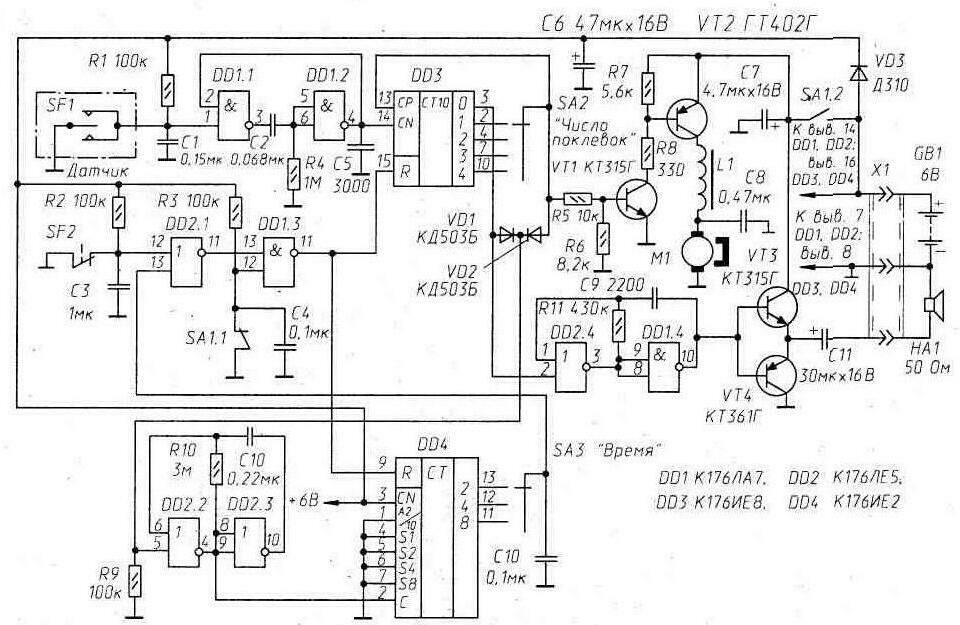
Fig. 2. Schematic diagram of the machine
The elements DD1.1, DD1.2, C2, R4 constitute a single-shot, eliminating false account DD3 - counter "bites" - from "chattering" contacts sensor SF1. On the elements DD2.2, DD2.3 assembled generator clock pulses, following with a frequency of 1 Hz. Counter DD4, summing these pulses, sets the active state of the automaton. Reset counters, reset the machine in its original state is the standby state is carried out by pulses "single" amplitude generated by the elements DD2.1 and DD1.3. This happens or at the end of active time (when a voltage of high level on engine switch SA3), or at the beginning of the strike (at break contacts SF2), or when you manually turn off the machine by the SA1 toggle-switch - circuit contact a pair of SA1.1.
On the elements DD2.4, DD1.4 and transistors VT3, VT4 assembled driven (input 2 of the element DD2.4) tone the alternator, exciting the dynamic head of HA1, signaling the angler about the transition of the machine in the active state.
Transistors VT1 and VT2 - electronic key control motor M1. The inductor L1 of the LC-filter is wound on the annular magnetic core (outer diameter - 10…12 mm) ferrite with m=1000…2000. His coil contains 50…100 turns of wire sew-2 0.2…0.3.
Flat power spring (2 in Fig.1) is the main mover of the machine is made of phosphor stripes bronze with a thickness of 0.8 mm. Its width is 78 and length (without sealed ends) - 220 mm. which is Created by the initial spring force at cutting - 1.3 kg, "max" up to 750 mm.
Node 7 is the usual terminal with a hole for the passage of fishing line.
The dimensions of the contact brackets not critical, it is only important that between her pads and moving end between the rocker arms it was possible to set the desired clearances: minimum - 1 and a maximum of 10 mm. the position of the rocker arm relative to the contact clips can be changed by tightening or loosening the springs in the 5 nodes. General mechanical strength all of these elements must be sufficiently high, since they "hold" the fish. At least 10…15 kg jerks and shocks they are required to carry without consequences. Screw-axis, where swinging rocker, he should have minimal resistance.
A release device of the machine and its placement details in the case pieced together from a sufficiently thick (8 to 10… .mm) sheet of organic glass or high impact polystyrene in the form of a box with a slip cover as shown in Fig. 3, and. The motor 1 is any compact low-power, for example, from the electric igrushki with the axis of the pinion gear 7 with a diameter of 5…6 and a length of not less than 5 mm (according to her, vivencias of earrings should free to move the large gear 4).
Before installing the motor you must check the quality of insulation of its rotor windings - resistance leakage must be less than 1 MOhm.
Right large gear gearbox providing four to five times the slowdown may be in the same toy.
Other details of the trigger devices: 6 - reducer shaft (steel); 2-it internal support (it is attached at the "bottom" of the case); 3 - soft flat spring on the shaft, pushing it outward; 5 - a bronze or brass bearing, pressed in the wall of the housing.
Earring clutch shaft gear with the pull of the springs can be run on an embodiment shown in Fig. 3, b. In this the case in the housing cover must be drilled with a diameter of about 25 mm (his position in Fig.1 marked by arrow A), through which, the rotating big gear reducer finger screwed the end of his shaft in the earring. This hitch is very high reliability, it is practically not affected by any outside influences. In another embodiment (Fig. 3, in) stud earring, carving in which was preserved only in the the lower part of its elliptical hole, just throw on a protruding from the housing, the shaft end of the gearbox.
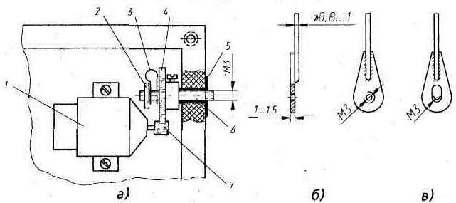
Fig. 3. Design elements
Sweeps begins with the appearance of "1" - voltage close to the voltage on the engine switch SA2. This tension blocks the counting input of the counter DD3 (MS; signals from the sensor SF1 can not change its state) and opening electronic key made transistors VT1, VT2, the electric motor M1. 8…10 times its rotor node "reducer shaft-earring thrust" disengagement and force spring, abruptly stands up, makes a cutting. But already at the moment of this separation host (contact pair SF2) at the inlet 12 of the element DD2.1 there is a "single" the tension that leads to the appearance of "1" and the input R of the counter DD3. As a result the counter returns to its source, the "zero" state, the engine switch SA2 is restored to "0" (voltage close to the zero potential bus), transistors VT1, VT2 are closed and the electric motor, making only right turns, turns off.
Reloading machine produce when the switch SA1: it is short-circuited in this position of the contact pair SA1.1 "holds" the electronics of the machine in prelaunch state.
Lag machine i.e. the time between the appearance of the signal 1 on the engine switch SA2 and the actual the bite depends on the speed and power of motor (it can be heavily boosted), slow gear, the number of threads of the shaft, put in the earring, lubrication of the rotating parts and, of course, the condition of the power source. In made instance it does not exceed 0.2 seconds.
The sensitivity of the sensor SF1 - 10 g/mm (force - out, move - in contact clips). It depends from the softness of the springs rocker.
The power source of the machine, equipped with a 4-volt motor (from an unidentified toy) to be a battery of four electrochemical cells or batteries, are capable of at short-term is low (a few tenths of a second) to give a current of 0,5…1 A. For the afterburner of the motor supply voltage may be higher. But certainly not above the maximum permitted for circuits of the machine.
Described electronic machine for a long time was tested at the marine experimental station of the Institute of marine biology, far Eastern branch of RAS (the waters around Popova, Reinicke, Rikord, etc.). The fishery was conducted mainly bottom fish at depths of up to 20…25 meters. And although features sea fishing - pitching, the displacement of the boat in the wind, the irregularities of the bottom, additional interference is set before the machine is quite a difficult task, he practically in no way inferior and experienced anglers. And often demonstrated their superiority… Machine also differed neat, almost never not damaging vital tissue by cutting. It was a pleasant surprise since the fish was caught and transplanted into the aquarium.
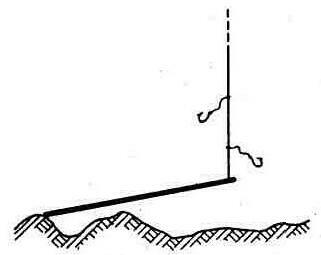
Fig. 4. Tooling machine
The picture shows the normal tooling machine close to that adopted in Primorye: basic scaffold 0,7… 1 mm leashes - 0,5…0,6 mm length 3…5 cm, single hooks No. 10…12. But sinker otherwise: steel rod diameter 6…8 and a length of 250 mm or more. Such sinker and his position at the bottom allow you to keep the line tension is almost constant and visible excitement. But this is in addition to the electronic "reflections" of the machine. Fishing same fish in Pology" actually he was not at issue. About real sensitivity the machine can be judged on the minimum weight the catch - 50 100… G. Maximum weight of fish was limited to the strength of the reins.
Publication: www.cxem.net