


")

The creation of devices with remote control various electronic actuators were promising direction in electronics more during my "pioneer" of childhood in the 1980-ies. Then, under the guidance mentors, we enthusiastically collected this hardware using discrete components. Usually she had the range of 5 - 6 m and barely could fit in the box size HH mm. If it was possible to assemble at least a fortnight equipment remote control model boat or plane the transmission range of teams of 20 - 30 m, it was considered (10 - 12 years guys) a great success.
Not lost its relevance in this direction today. But now it to make it easier, because you can not collect in detail, and to purchase in store ready-to-device signal transmission over the air (using the IR channel, laser beam, etc.), and for a very "reasonable" price and adjusted own tasks, improving it.
Of course, it is regrettable that almost negated creative part of creating a device, involving painstaking understanding in question its operation - from design to configuration, not only improves skills, but also opens the door to in-depth fundamental research.
But, on the other hand, why waste time and "suffer" is to create a device with zero, if it is possible to improve ready, extending the range. Like this an approach is acceptable for professionals or those who need to quickly get the practical result of their work. These are the realities of time, and under them it is necessary reasonably to adapt.
Invite readers to consider a remote control device, current over the air for a distance of over 100 m and allowing to automate enabling and disabling the discharge submersible water the pump that supplies water to the house, a bathhouse, a barn and other buildings infield from the source - the village well.
The unit can be purchased in the store household goods wireless radiosonic value-192 rate. I note in passing that it is ready equipment pump station control (without wires) is worth more than 3,000 rubles. Draw your own conclusions. However, it is able also to perform automatic monitoring of water pressure in the circuit when it drops (open the tap in the house), in command of filling the reserve tank, and some model - and water heating. But in our case these features were unnecessary.
The electrical circuit of the receivers of radiosondes
Electric scheme prefix
Wireless calls may have different appearance, but in their composition required elements are the transmitter and the receiver. As a rule, such wireless calls operate at a frequency of 433 MHz and do not create interference. Besides the power of their transmitter is small.
Declared by the manufacturer in the passport range purchased radiosonde is 50 m. However, in practice this distance is significantly less, even if the transmitter and receiver are mounted in line of sight, without any barriers between them. Normally, this figure should be divided by three.
With the increase in the stated range of radiosondes increases and their retail price. For example, wireless bell with a radius of 100 m (in the realities of 35 m) is already more than 1,100 rubles. But to acquire such and not as an Amateur, in fact, anyway, what type of call to be improved, developing its range. So consider the simplest is the "budget" option.
The first thing you need to remove the housing cover on the radio, because to increase the range will be on it. Its antenna will not touch, because at a frequency of 433 MHz radio signal its length has virtually no effect on the increase distance work the ligaments transmitter - receiver.
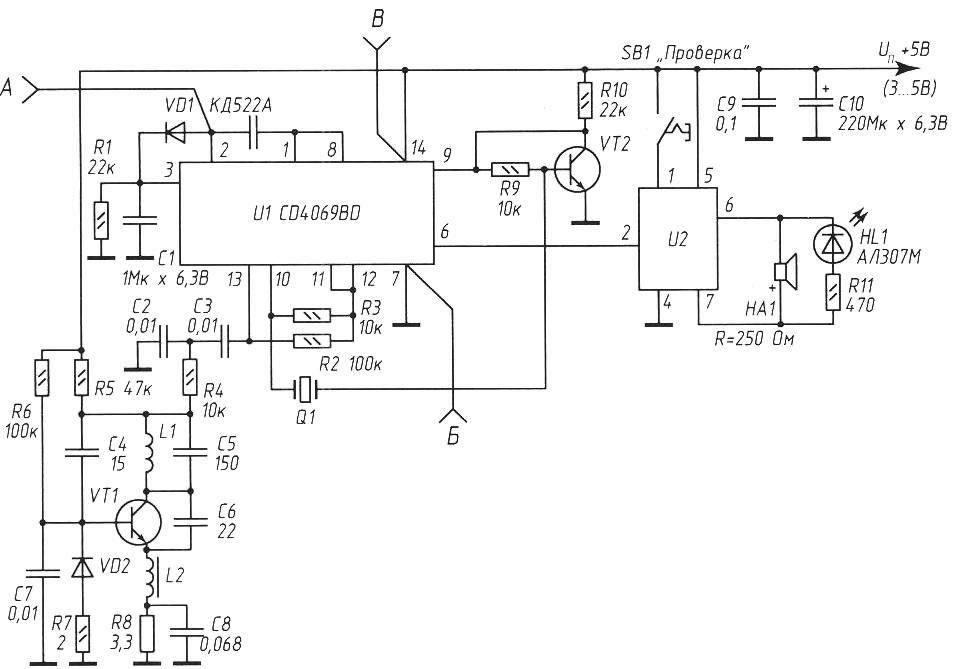
The photo shows the receivers of radio signals with the cover removed - two characterized by the appearance model. But the scheme they have one (presented on p. 21), although performance on the circuit Board is different, in particular, on one of the photos presented version, assembled from discrete elements, and the other from elements in the SMD package for surface mounting.
Pin 2 of U1 has an active high level at admission radio receiver (when pressed). Pins 1 and 8 of U1 - on the contrary: high level - at rest, while a low logic level when receipt of a control signal. These two signals can be used to control devices of the load with the help of simple consoles.
To the remote pump operating efficiently (the first press of the transmitter button the pump connected to the network 220 In, and when repeated click was disabled it), you will need to collect additional simple the device and connect it to the final circuit (Board) receiver industrial wireless call.
Improvement of the receiving unit
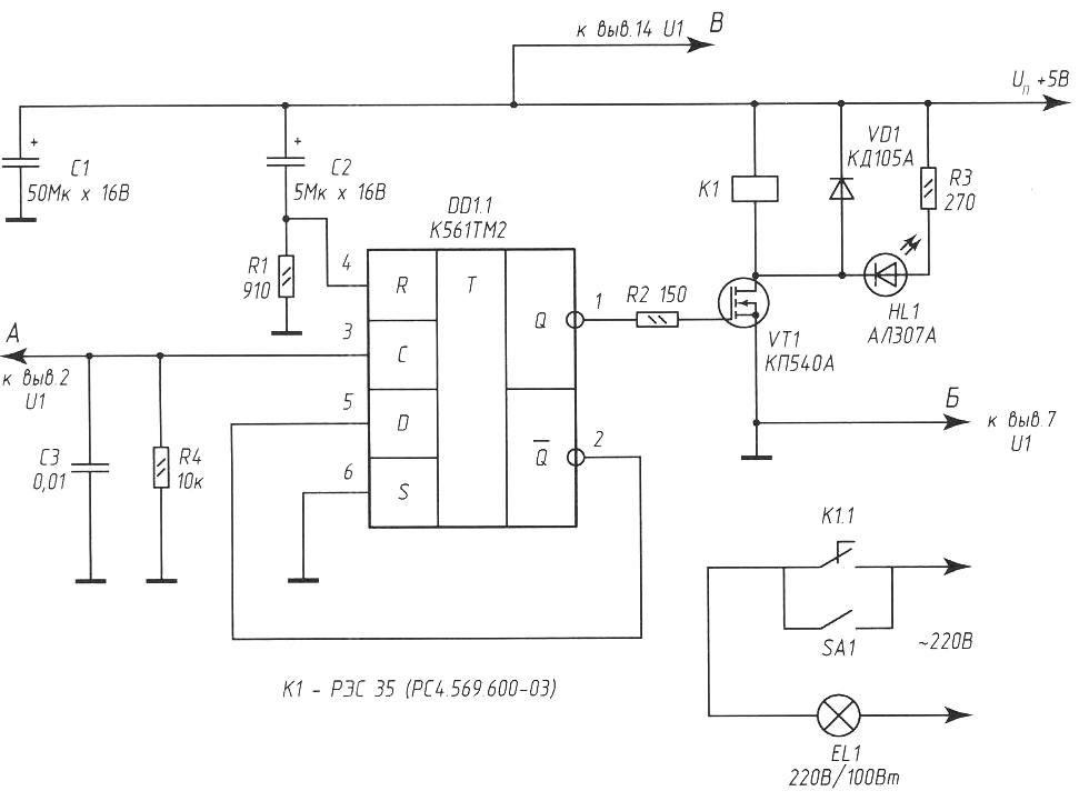
In the diagram (below) is a circuit diagram of consoles (more device) receiver of the wireless call.
In parallel to the lamp filament ЕL1 connect a submersible pump (not shown) with a corresponding reinforced hose that stretches to the house from the well. Lamp ЕL1 is an additional indicator light pump, thanks she can distance to make sure that the command received from the transmitter, the remote worked, and the pump came on.
The output of the console is connected to the base circuit Board of the receiver radiosonde unshielded wires type MGTF-0.4 (or similar) connect the common wire (to the minus power supply) and pin 3 of the element DD1 chip.1 (KTM) to pin 2 of the chip CD4069BD (on some models D4069UBC). Domestic analogues of these chips - CRL and CLR.
When receiving a radio signal from the transmitter (its duration is about 2 to is provided by the transmitter-keychain regardless of the length of exposure on its button) at pin 2 of chip CD4069BD (U1), the signal level changes with low to high. Pin 6 and 7 of the chip U2, which is the generator of tunes connected to a low-power dynamic head.
Thus, during transmission of a signal through a radio channel not included melodious call, enough to sever the printed conductor from pin 7 U2 to a dynamic capsule. Or unsolder one of the conductors leading to it.
The electrical circuit of the transmitting node radiosonde
The basis of the device is the trigger on one popular element of the chip KTM. Without going into the details of her work (it is written a lot of articles), the main thing I note: in this IC chip, two D-flip-flop containing two inputs asynchronous control S and R. the Trigger is switched by a positive differential clock input (pin 3 DD1.1). Thus the logic level present the input D is transmitted to the direct output Q. When a high logic level at the input reset R trigger reset. The supply voltage can be within 5… 9 In (about the experiment to increase the voltage of the receiving unit is below).
Now, knowing the chip DD1.1, it is possible to understand the General principle of operation console. When the power input R DD1.1 in the first moment, thanks discharged the capacitor C2 goes to a high logic level, which resets the trigger on the direct output Q becomes the low level voltage. Transistor \/T1 is closed, relay K1 is de-energized, the lamp ЕL1 is not lit, the pump is not works.
About a third of a second (this is due to the oxide capacitance of the capacitor C2 and the resistance of the resistor R1) of the first charged almost to the supply voltage, and the level at the input R (pin 4 DD1.1) will change to low. Now the trigger is ready the reception signals to clock input C, having, as appears from the scheme, low the initial level.
When the radio signal from the transmitter from the receiver is input With chip DD1.1, from the schema of the remote call goes to a high level voltage. Consequently, the trigger is thrown in more sustainable the state is now at its direct output Q high voltage level. Transistor VT1 activates the relay K1 and contacts, in turn, complete the electrical the power circuit of the lighting lamp EL1 and submersible pump. In this state the trigger is as long as desired, until the next positive front the pulse at the input, upon receipt of which (next key on the remote-transmitter) the trigger returns to initial state - lighting lamp ЕL1 goes out, the pump is de-energized and off.
Chain С2R1 provides relief trigger DD1 chip to its original standby at power-up. Oxide capacitor C1 performs the function of filtering element nutrition. The VD1 diode prevents surge reverse voltage when to switch on/off relays.
The total capacity of the public switched load depends on the parameters electromagnetic relays K1 and in our case is limited to 350 watts.
Since the number of discrete elements of the small consoles, all of them mounted on the section of perforated Board size 30x40 mm and with the connecting wires are placed in the standard case and the receiver call in the elements of Autonomous power. To reduce the effect electrical interference it is desirable that the wires connecting the device with the power source and going from the relay K1 to the pump, had a section not less than 1.5 mm and the minimum length.
Details
Fixed resistors MLT-0,25 (MF-25). Oxide type capacitors C50-26 working voltage of at least 16 V. the Remaining non-polar capacitors type km-6B. Chip DD1 (CTM) can be replaced CTM without compromising efficiency work site, but in this case it is necessary to change the scheme, as these conclusions chips have a different purpose. Further details about this option replace can be found in reference books on modern CMOS chips. Transistor VT1 - field, with a high input impedance. This minimizes the current leakage in the standby state of the radio signal and has virtually no impact on the trigger output, despite the limiting resistor R2 with a small resistance.
Relay K1 can be replaced RES (RS4.569.201) or more, calculated at pickup voltage 4…4.5 V and current 10 to 50 mA. Set in relay with current of 100 mA is undesirable, as the Manager relay the VT1 transistor has a finite capacity.
Receivers of radiosondes with the covers off: and - from a discrete element; b consists of the elements in SDM-buildings
Instead CPA you can apply field-effect transistor of any of the series or K foreign counterparts BUZ11, IRF510, IRF521. Led НL1 - anyone using it convenient to control the relays and the circuit Executive contacts. If necessary, the elements Ni and (R3 can be excluded from the scheme without consequences. Additional (manual mode) the pump switch in the diagram shown below the designation SА1.
Coil L1 - frameless 4 mm diameter of 1.5 turns of silver coated wire with a diameter of 0.8 mm (turn to turn). The inductor L2, type D-06 with the inductance 82 µh (microhenry).
The basic version provides an Autonomous power supply - 2 AA element 1.5 V. But in the conditions of recommended use of remote call best stationary exercise power from a regulated source power supply voltage of 5 V with deviations not exceeding ± 5%. Such a source may be, for example, the stabilizer on the chip CREA. Current consumption transmitter in active mode - 35 mA. Current consumption from the power source the receiving unit in a constant standby mode does not exceed 10 mA and increases up to 50 mA when enabled, is specified in the scheme relays. Other relay types current consumption may have a different meaning.
Attention!
The optimal supply voltage of the receiver 5-9 V. to Increase the voltage the receiving unit is not necessary, because the range of the device from this innovations not increased (verified experimentally by bringing the voltage to 12 In).
A transmitter itself, outwardly representing the body in the form of a key ring, the size of a standard matchbox, refinement is not needed. Not change once a year battery (the same kind installed in most transmitters, keyfobs, alarm systems for cars - 12, AE, manufacturer GP Ultra or similar), the power transmitter carried out using any industrial adapter with output stabilized voltage of 12 V and a current not less than 0.5 And, for example type TV-182-S.
Tuning coil L1 with armored core inside. The diameter of the outer coil 4 mm, the winding 5 turns of silver coated wire with a diameter of 0.8 mm.
L2 - choke type D-06 with the inductance 82 REAG.
Transmitter antenna worthy of detailed description. To increase range work to the antenna contact on the circuit Board using a piece of wire MGTF-0,8 (or similar) solder telescopic whip antenna for radios (available in stores). Or, at least, that immeasurably worse - to use as an antenna similar to regular stranded wire having a length of 350… 400 mm, fluffed at its end, as the petals flower, thin wires (diameter of the "flower" - 60…80 mm).
The most effective range telescopic antenna (in practice) will be in that when the "telescope" pushed to the middle, i.e. on the same 350… 400 mm.
Now, provided the recommended improvements of the antenna in the transmitter device it is possible to obtain operating range up to 200 metres line of sight or remotely to control a pump or other resistive load, the choice of which limited to the parameters of the actuating relay and imagination of the author.
Author: A. Kashkarov