Amateur fishermen know that bass and other fish are more willing to take the bait, if fishing line with a hook be forced to vibrate with a frequency of from 1.5 to 12 Hz.
Contactless small electronic fishing rod-jig allows for a wide choose the required frequency for catching different fish. It is easy to manufacture and does not require networking. All of its parts, including the power source, arranged in the housing handle.
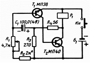
Diagram of the electrical portion of the rod (electronic unit) shown in Fig. 1. The master oscillator rods is an asymmetrical multivibrator, generating pulses of constant duration and amplitude. Repetition frequency pulses is adjustable from 1.5 to 12 pulses/sec change in the resistance variable resistor R1. The frequency of the pulses and their duration determined by the capacitance of the capacitor C1 and resistor R2.

Fig. 1. The block diagram of the electronic fishing rod
The use of transistors of different conductivity allowed us to generate a schema a minimum number of parts. The transistor T2 operates in key mode, and to the relay coil P1) during the working pulse is applied almost complete the battery voltage. The voltage drop at the collector of transistor T2 within desktop pulse is a few hundredths of a volt when the voltage of the source the power of 1-1. 5 V.
System, the adductor kevock in effect, serves as a low impedance solenoid-type relay The RS-4, RS-52, RES-10 RES-13, -22, etc. the relay Coil is wound with a wire PEV-1; 0,41-0,44 mm, the resistance is 2.4-2.6 Ohm. Current consumption electronic unit on average frequency of 30-50 mA. Variable resistor R1 with resistance from 4.7 to 10 ohms can be with switch and there will be no the need to use a separate button or switch.
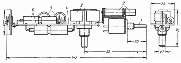
The location of parts on the circuit Board shown in Fig. 2 and additional explanation is not required. It should be noted that in this design used two in parallel included condenser type EM-50-M Hard the winding of the relay, variable resistance and the contacts for connecting the battery can be used for fixing and fitting all the other parts.

Fig. 2. The location details of the electronic unit on Board: 1 - the inverter; 2 - solenoid holder Assembly; 3 - push-button switch; 4 - payment; 5 - transistors; 6 - capacitors

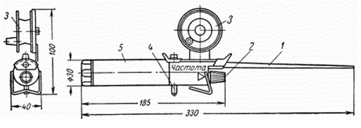
Fig. 3. The appearance of electronic fishing rod: 1 - rod; 2 - frequency control; 3 - coil; 4 - switch, push-button; 5 - housing
To anchor the relay soldered bullet casings from a small-caliber cartridge, which inserted the whip of vinyl plastic, nylon or other elastic material.
In Fig. 3 shows an external view of a fishing rod with a single coil. A power cell is one element FMC (6-8 hours). The basis of the electronic unit serves as a handle, which is a hollow cylinder made of foam, cardboard or other lightweight material. In the front of the housing of the handle made a hole diameter of 8 mm under the whip rods and installed a variable resistor. In the back - biasing the stopper element FMC with a conical spring. In the manufacture of pens it is necessary to leave a gap for free movement of the armature of the relay in the collected the fishing rod.
Properly assembled circuit begins to work immediately, if the gain transistors is in the range from 50 to 80.
The rod worked well when ice fishing in the Gulf of Finland, lake Peipsi the lake and in the suburban reservoirs.
The simplicity of the scheme and design makes it possible to fabricate electronic fishing rod to any novice radio Amateur.
Author: A. N. Masuk


