Simple electronic trap for insects can be collected using the lamp daytime running light 20-watt type LDS-20 and simplest Converter voltage. Lamp attracts insects with its light, arriving at which they fall between two grids surrounding the lamp and under high voltage. In addition, the heat generated by the lamp attracts insects.

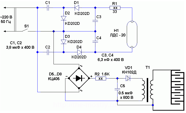
Fig. 1
To power the fluorescent lights used in the voltage multiplier, which rectifies the mains voltage to a value of approximately 600 volts (no load). The upper shoulder of the multiplier (the capacitor C1, diodes D1, D2) charges the capacitor C3, and the bottom (the capacitor C2, diodes D3, D4) of the capacitor C4. The upper capacitor is charged to a negative voltage, and the bottom is positive. Since the capacitors C3 and C4 connected in series, the voltage across them folds up and becomes sufficient for ignition of fluorescent lamps, and power current allows you to maintain it burning. In this scheme, the lamp power can be used as the backlight from the monitor, and fluorescent lamps blown filaments.
Rectifier (diode bridge D5...D8) pulsating voltage 50 Hz is supplied to the voltage Converter, made on the diacs VD1, the capacitor C5 and the resistor R2. Load of the Converter is the primary winding of the transformer T1.
Does the voltage Converter as follows. The capacitor C5 is charged through the resistor R2 pulsating voltage, and as soon as the DC voltage on the capacitor reaches the value of about 80 volts, the dinistor VD1 opens and the capacitor C5 is rapidly discharged through the primary winding of the transformer T1. Such a Converter is called a relaxation oscillator. In his scheme the resistance of the resistor R2 is chosen so that the current flowing through it will not hold dinistor in the open state after discharge capacitor, hence a dinistor closes and the process repeats itself. Frequency the operation of the Converter depends on the parameters of the elements R2, C5, and trigger voltage dynistor VD1 and in this case it is a few hundred Hertz. As the number of turns of the secondary winding of the transformer T1 is many times more than the original, and a pulse voltage on it will be much more reach several kilovolts.
As pulse transformer used ignition coil from a car, type B or similar, in this case, the high voltage output is upper circuit on the output of the transformer T1. Instead of the ignition coil can use a homemade transformer wound on a ferrite segment rod brand with permeability of 400, length 80 mm and diameter of 10 mm. the Primary winding has 30 turns of wire PEL-0,6, secondary - 1500 turns of wire PEL-0,08, winding in 10 layers with careful insulation between layers.
Capacitors C1..C4 should have a working voltage not lower than 380 volts, the capacitor C5 is not below 750 volts. Instead of the diode bridge (D5...D8) use diodes type CDA, CDA or similar.
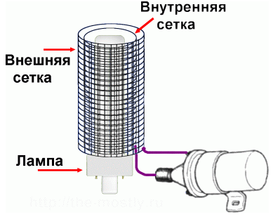
High-voltage grid with a cell diameter of about 10..20 mm is necessary positioned around the bulb of H1, so that they formed two cylinder, the distance between these grids should be slightly greater than the distance at which electrical breakdown occurs. For external security mesh traps should to be connected to the housing of the ignition coil. The internal diameter of the mesh needs to be sufficient to prevent electrical breakdown between the grid and lamp N1.

Fig. 2
If this trap is to place the source with carbon dioxide, such as used in the simplest trap for the mosquitoes, made of plastic bottles, the effectiveness of electron traps will increase significantly - it will fly more mosquitoes.
The scheme of electronic traps for insects can be considerably simplified if, instead of fluorescent lights LDS-20 and a voltage multiplier circuit (a resistor R1, capacitors C1...C1 and the diodes D1...D4) to apply the so-called "energy saving" lamp 15 watt with built-in electronic ballast.


