


")

In my opinion, the most effective seem to be those developments that do not you need to raise from scratch: we will focus on the improvement of industrial electronic devices on their own. The result is quite modern workable designs, one of which I offer. It an additional node to the industrial flash SEF-1 produced once millions of "copies".
Its basis - flash lamp IFK-120 and the oxide high voltage capacitor large capacity. Transformerless voltage Converter when use it on 220V allows you to accumulate on the capacitor plates a charge of several hundred volts (when the readiness of the flash) the owner warns burning neon gas discharge indicator on the body flash. The capacitor discharge occurs due to the closure of remote contacts (in the control circuit of the thyristor device) intended for connection to the camera. This feature I used for flash control "from the outside".
Since the control circuit of the thyristor (anode circuit which includes winding pulse transformer), the potential difference does not exceed 10, the control electrode I connected the output of the multivibrator on the chip CREW collected according to the classical scheme. Now we only have to ask the desired frequency of the pulses, which "converted" to their corresponding flash lamp IFK-120.
Figure 1 is a circuit diagram of the multivibrator on the chip CREW included in the oscillatory regime, and simple sets generator with adjustable parameters of the output pulses in a wide the limits (i.e. the generator of the universal destination with little effort the output stage it is effectively used as a high frequency Converter voltage for the flash SEF-1).
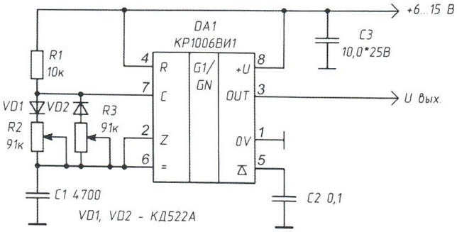
Fig. 1. The electrical circuit of the multivibrator on the chip CREW included in the oscillatory regime
Let us consider the operation of the multivibrator. When power is applied to the circuit elements the capacitor C1 has a very low resistance to current flow and starts charged via the resistors R1, R2 from the power source. At the first moment at the entrance run (findings 2 and 6 DA1) there is a negative pulse, and the output chip (pin 3) sets the voltage of the high logic level. The voltage on the charging capacitor C1 is growing exponentially with the time constant t=RC, where R is the sum of the resistances R1 and R2. When the voltage on the plates of the capacitor C1 reaches 2/3 of the supply voltage, internal the comparator resets the trigger circuit to its original state, and the trigger in its turn, rapidly discharges the capacitor C1 and switches in the output stage the low state voltage. Thus, the periodic charge the capacitor C1 through a chain of resistors R1R2, and the discharge - via the resistor R3. This allows you to adjust the duty cycle over a wide range, by setting the ratio between the resistances of the resistors R1 and R2.
Ramasadaya resistors R2 and R3 determine the parameters of the pulse generator and its frequency in wide range: R2 adjusts the burst pulse (the smaller the resistance, the shorter tutus, down to single pulses), R3 adjusts the pause between pulses from 0.5 to 30 s. the parameters of the pulse repetition rate is also depend and on the capacitance of the capacitor C1, which can be applied to hundreds of UF. In this mode the voltage on the plates of the capacitor C1 is changed from 1/4 to 2/3 voltage of the power source. The charge rate of the capacitor and the threshold internal comparator is directly proportional to the supply voltage, so the duration of the output pulse of the supply voltage is almost independent. The output of the timer CREW switches, dramatically changing the voltage at pin 3 DA1. Pin 5 of the chip should be left free or be connected to GND through the condenser type km with a capacity of 0.1 μf. In this scheme it is not fundamentally.
Oxide capacitor C3 smoothes the ripple voltage from the power source. The output current of the generator on the chip CREW (pin 3 DA1) does not exceed 250 mA, that for many Amateur designs is enough. To connect this prefix can be directly to the pulse transformer of the flash. However to control high-voltage pulse load with the necessary Converter galvanic isolation (scheme in Fig. 2) - he will need to "domestication" other (also reviewed) types of flashbulbs.
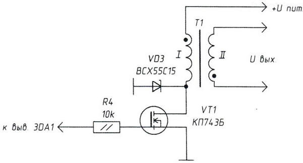
Fig. 2. The electrical circuit of the output stage voltage Converter
Converter cascade is implemented on a field-effect transistor VT1, in the circuit source which included the winding of the boosting transformer T1 of the flash. For additional protection of the output stage in the circuit to the transformer is applied supressor (protective Zener diode) from X with any letter index. A protective Zener diode must have a voltage stabilization not less than 3/4 u pit.
Chip when working may be slightly heated to 30° - 40°C. the Element power devices can be stand-alone (battery type "Crown" with step-up voltage Converter for flash lamps) and stationary - power supply with stabilized voltages between 6 - 15 V.
About the details. Field-effect transistor VT1 can be replaced with IRF640, IRF511, IRF720. The variable resistors R2, R3 with linear characteristic of resistance - multi-turn, for example, SP5-1VB. Instead of the oxide of the capacitor C3 is suitable type K50-29 or similar. Fixed resistors - type MLT-025, nonpolar capacitors - type km.
Practical application of the combined device may be different. Except the first that comes to mind of a young man set it on the dance floor in the strobe pulse frequency multivibrator in this case, select 1 - 10 Hz), there are other options. For example, I now use the device for remote indication of normal operation alarm village houses. In case that my farm is separated from the village for several kilometers. Message - the forest road. But due to the fact that he is up on the hill, visible from the village the farmstead. But, of course, difficult to see - there's extraneous. And this important because the majority of the time I live in the city, many miles away from farm. But periodic bright flashes (the pulse repetition rate of 0.1 Hz) flash lamp IFK-120, together with the reflector directed towards the closest houses will be informed about the state of Affairs when someone get into the house - the alarm goes off, driven by me using a cell phone (on distance), flash lamp will stop flashing and will serve as disturbing signal.
After installation and connection of the considered devices only to negotiate with local residents that they would look at my farm. Their main task, of course, is not to pinpoint the time of the alarm (I'll immediately, as well as the local police Department, which will go calls from a cell phone that is installed in the estate and acting as "remote notification"), and to track and try to remember the identity of those "good" people, that soon will proceed on foot or by car from my farm. A matter of law enforcement.
During the day, and especially at night, flash IFK-120 is very well visible on the distant the distance that can be used in other cases when you need remote annunciator.
Another option is the use of hybrid designs is the protective function the owners of the house. The flash is in the hall (just behind the front door) reflector to the output, the power supply to the device by using ordinary wall switch. If included guest turns out to be, to put it mildly unwelcome, it is easy by pressing the switch, impact flash lamp, included in strobe mode. He will be paralyzed in the actions contactless (his life while not in danger).
The device can adopt not only in rural houses, but in urban apartments. And there may be more extravagant options. It's all in imagination and its skillful implementation.
Author: A. Kashkarov