Use for electronic engraving of high frequency current at high the voltage enables the engraving is very subtle touches like the tree and other amplepuis materials.
The engraving process is based on the passage of currents of high frequency (80 kHz and above) through small parasitic capacitance, wherein between the edge of the cutter and engrave surface electrical arc is generated.
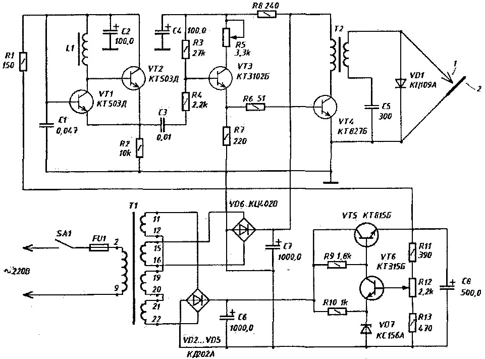
The engraving process provides a great opportunity and requires less effort than burning. A source of high frequency current is a generator, the electrical circuit which shown in the figure.

(click to enlarge)
The master oscillator is assembled on transistors VT1 and VT2. Transistor VT1 provides the gain of the feedback signal taken from the resistor R2.
The frequency of the oscillations determines the input and output conductance of the transistors VT1 and VT2 and the inductance of the coil L1. The change of the oscillation frequency is due the changes of conductivity of the transistors when changing the supply voltage.
Power master oscillator-from the adjustable voltage regulator the transistors VT5 and VT6. Changing the output voltage the resistor R12, adjustable frequency of the generated oscillations within 80...150 kHz. Signal from the master oscillator through the emitter follower transistor VT3 is fed to the output stage transistor VT4, in the collector circuit of which included the primary winding of the transformer T2. The voltage from the secondary winding is fed to the cutter. The cutter is a rod with a sharpened end, inserted in the holder, made of Teflon or other material. The lower end of the secondary winding of transformer T2 is connected to the metal the electrode 2 through the capacitor C5. which protects against short circuit when you touch the cutter 1 of the electrode 2 in the excitation of the arc. Thanks the inclusion of the diode VD1, the cutter will be a negative pulse high frequency voltage through the parasitic capacitance in the material to form an arc.
Details and design
Power transformer T1-type TP-220-50.
As the coil L1 is applied to the standard throttle type DM-01 inductance 450 µh.
The electrolytic capacitors C2 and C8 type K50-6, designed for a voltage of 25 In, and C4, C6 and C7-for a voltage of 50 V.
Transformer T2 is made on the core of the transformer horizontal TVSL the Primary winding has 28 turns of wire PEL-2 0.8 mm, secondary -550 turns of wire PEL-2 with a diameter of 0.3 mm. the Secondary winding of the transformer wound layers, the layers are separated by strips of insulating paper. Ready the coil need to be impregnated with paraffin.
Setting
The establishment of the generator is reduced to the setting the optimal frequency at which the generator gives the most power and is stable.
Engrave the product is pressed to the metal electrode, bring the cutter, an arc is formed, and the resistor R5 set the required power of the generator in depending on the thickness of the strokes.
Attention! When working with the generator, you should be careful.
Author: V. Yakovlev, UT5WK, Shostka


