The house had matches, and in the store they did not deliver. Not trouble - simple lighter for kitchen stove can be assembled from a dozen non-deficient radioactive elements.
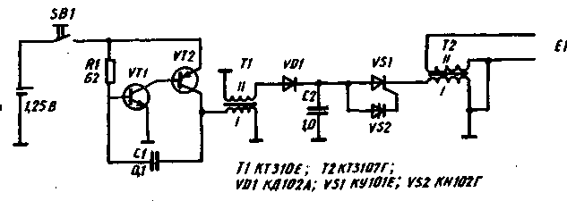
Scheme lighters (Fig.1) consists of two generators. The first is built on two low-power transistors, the second - on two the thyristors. The cascade transistors of different conductivity converts low voltage constant voltage in high-voltage pulse. Timing chain in this the generator element is used With 1, R2. When you turn on the power transistor VT1, and the differential voltage at its collector opens the transistor VT2. Capacitor C1 is charged through the resistor R1 reduces the base current of the transistor VT2 so that the VT1 transistor comes out of saturation, and this leads to closing and VТ2. The transistors will be closed until such time as the capacitor C1 is not discharged through the primary winding of transformer T 1.

High impulse voltage taken from the secondary winding of the transformer T1, rectified by diode VD1 and arrives at the capacitor C2 of the second generator with SCR VS1 diacs and VS2. In every positive half cycle of the storage capacitor C2 is charged up to the peak value of the voltage equal to the voltage switching dynistor VS2, i.e., up to 56 In (nominal pulse gate trigger voltage for the SCR type KN G).
The transition dynistor in an open state acts on the circuit management dynistor VS 1, which, in turn, also opens. Capacitor C2 discharges through the SCR and the primary winding of transformer T2, and then a dinistor and SCR will be locked again and start the next charging of the capacitor the switching cycle repeats.
From the secondary winding of transformer T2 pulses are removed the amplitude of several kilovolts, which is introduced through the tip of the lighter in a special camera that is experiencing the high-voltage spark discharges, igniting the mixture of gas with air. The frequency of spark discharges equal to about 20 Hz, but she much smaller than the frequency of the pulses taken from the secondary winding of the transformer T1. This happens because the capacitor C2 is charged up to voltage switching dynistor (ICDP.) not for one but for several positive halfcycles. The capacitance of this capacitor determines the power and duration of the output bit pulses. Safe for diacs and the gate electrode of SCR average value of discharge current chosen from calculate the capacitance of this capacitor and the magnitude of the pulse voltage, supply cascade. For reliable operation denistone-trinistorny generator must to strictly maintain the ratio: u pit.imp. Uрпк. To comply with this condition the capacitance of the capacitor C2 must be in the range of 1 µf.
Of the ten parts of the device two - hand-made: the transformers T1 and T2. The first is made on a ferrite ring magnetodipole size HH. He has 540 turns of wire sew-2 0.1 grounded outlet after 20 turns. The commencement of its winding joins the transistor VT2, the end to the diode VD1. The second transformer is made on the a coil with a ferrite (except from permalloy) core with a diameter of 10 mm, length of 30 mm Coil with an outer diameter of 30 mm and a width of 10 mm is wound wire sew-2 0.1 to completely fill the frame. Before the end of the winding is grounded outlet, and the last wire range from 30-40 turns is wound a coil to a coil on top of the insulating layer of varnished cloth. Beginning winding of the transformer is attached to the high voltage electrode discharger, and the end to the cathode of SCR VS1. The transformer T2 on the go winding need to be impregnated with an insulating varnish or glue BF-2, then dry thoroughly.
Other details of the scheme can be replaced without compromising reliability work lighter. So, instead of VT1 and VT2 can use any low-power transistors, capable of operating in a pulsed mode.
SCR CUE can be replaced by CUG. Power source - elements with a maximum voltage of 1.5 V. It can be type elements 312, 314, 316, 326, 336, 343, 373, and disc batteries D - 0.26 D, D-0.55 C etc.
Special care requires the fabrication of high voltage camera discharger. The gas must penetrate to the electrodes, mixing well with who of the spirit or even the most powerful spark discharge will not ignite. Therefore, the camera must have a Cup shape with drilled in its end and the sidewalls of the holes. The body-stocking for it can serve as aluminum shell from oxide electrolytic capacitor type K50-35 with a diameter of 12 mm. After the high-voltage electrodes, missed through a remote hollow rod lighter (outer core diameter is 9 mm), securely isolated from each other, and the distance between their ends adjusted for sufficient strength and size of the sparks at the end of the rod put the camera glass. Openings for passage of gas drill drill 3 mm.
The device can be collected in any appropriate the case, in the author's version - the case of industrial piezoelectric lighters.
Author: Y. Kalentev, Minsk; Publication: N. Bolshakov, rf.atnn.ru


