


")

Hand drill electric machine (electric drill) there are many house masters. But it would be wider if it is to provide a regulator the frequency of rotation. In this case, the tool, in addition to its direct purpose, can be used as a screwdriver, and as a machine for winding coils. In particularly, the design of drill IE-A allows you to embed electronic regulator in its end face in the place where is located the entrance the capacitor and the trigger button and variable resistor to set in the handle tool.
The regulator consists of a managed bridge diodes VD5, VD6 and triacs VS1, VS2 (see circuit diagram) and the control device on unijunction transistor VT1. Through ballast resistors R1, R2 on it goes pulsating voltage from the rectifier unit VD1, connected to the network via button SB1.
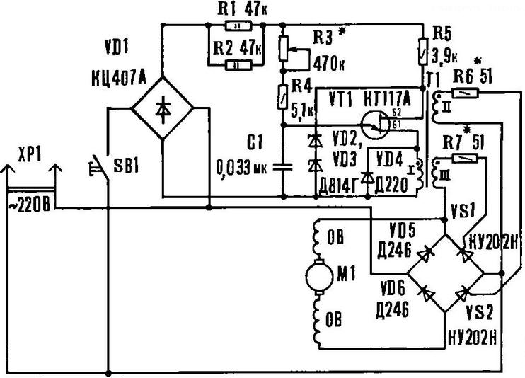
Schematic diagram of the electronic controller
The input VT1 included integrating the chain R3R4C1. At the beginning of each half cycle begins the charging process of the capacitor C1, and the voltage across it increases to the moment you open the transistor, then C1 is discharged to the primary winding pulse transformer T1. When VT1 is closed, the circuit of the secondary winding T1 pulses appear of the control current, which opens the triacs VS1, VS2. Off they are at the moment of passing the supply voltage through the zero value. Changing with the help of variable resistor R2, the charging time of the capacitor, set the interval during which opened thyristors, and therefore supplied to the motor power. The faster charging of C1, the earlier open the thyristors and the higher the frequency of rotation of the rotor.
Zener diodes VD2, VD3 limit the voltage across the transistor.
Circuit Board made from foil fiberglass (see figure). The resistors R1, R2, diode VD4 and wires to R3 and SB1 are with back side of the PCB, so in places they connect, you must install the pistons.
Circuit Board of the controller arrangement of elements
Pulse transformer T1 is wound on iron H (matching transformer radio "Mountaineer"). All three coils contain 300 turns of PEV-1 to 0.15. Special attention should be paid to mutual exclusion windings. Their conclusions stranded mounting wire. Fix transformer by using made of tinplate, clips, which tightens core. You can use industrial suitable pulse transformer sizes.
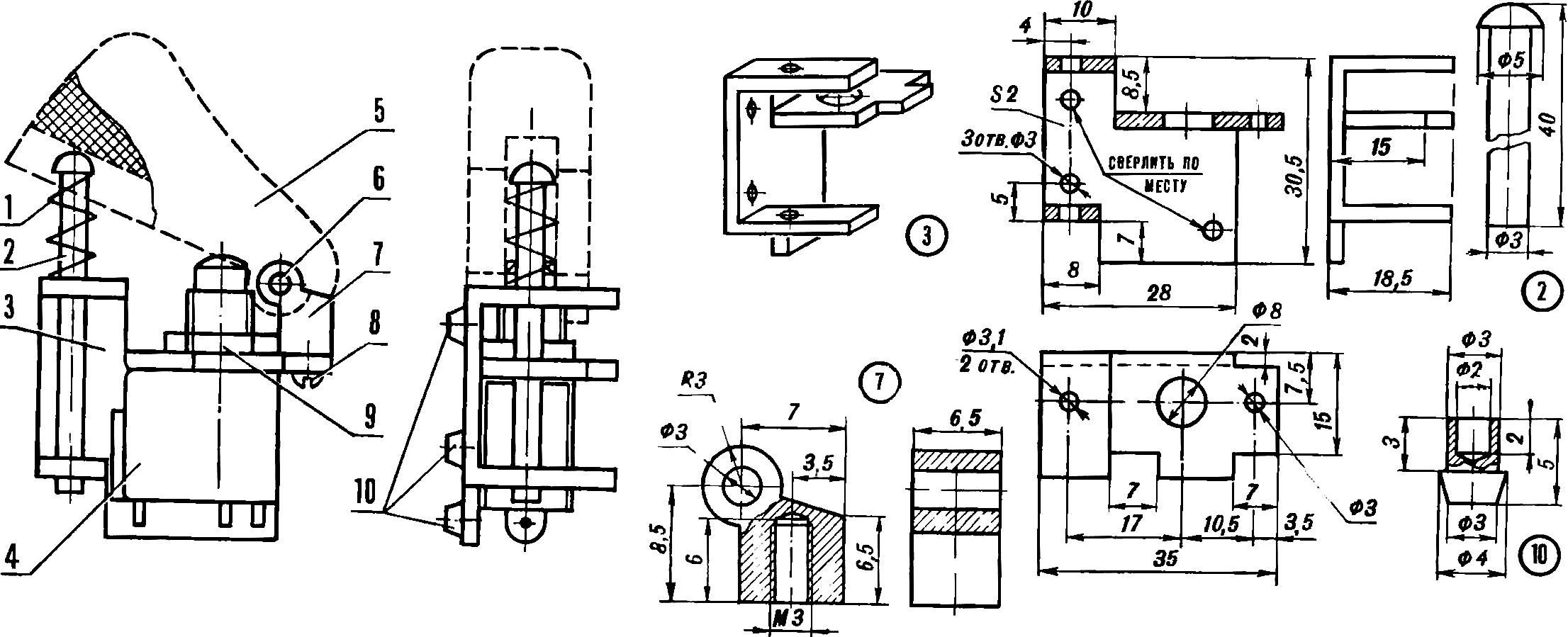
To accommodate the variable resistor R3 in the handle of the drill, it is necessary to replace the regular switch to other, smaller (see Fig.).
The base is made of steel sheet thickness of 2 mm. holes In the back side of the base are inserted and rasklepyvajut stops which serve to mounting the switch in the handle of the drill. On the inner side of the right half arm has three recesses Ø 4 mm under the regular stops of the switch. Base new switch your stops are inserted in the holes and pressed the left half of the handle of the drill. The provisions of the two stops is determined by the place that the trigger switch was located and moved exactly the same as before the alteration. To the base is attached to microcopy KM1-1 and tighten the M3 screw of the bracket. Last using the axis O 3 mm holds the hammer, which is translated to its original state pusher with spring. Spring, the trigger and the axis from the regular switch. The rest parts are made of steel St3.
Switch: 1 - spring, 2 - pusher, 3 - base, 4 - microcopy KM1-1, 5 - trigger 6 - axis 7 - bracket 8 - M3 screw, 9 - nut M8, 10 - stops.
Now in the formed in the handle cavity set variable resistor R3. To do this, in the left half of the handle, where there is a lock button, under he drilled the appropriate hole in such a position that the knob is not interfered with when working with a drill and it was easy to rotate with your thumb.
To the body of the drill are mounted on short struts, they are using glass fibre laminate washers (thickness 2 mm, diameter 6 mm) long and stands fastened fee. To the long racks, in turn, two M3 screws attached back cover drill (see figure).
Mounting Board regulator on the body of the drill (click to enlarge): 1 - drill 2 - short-hour, 3 - disc, 4 - hour long, 5 - mounting fee. In parentheses are shown the dimensions for the rack 4.
The establishment of the regulator is to select values of resistors R6 and R7. Setting produce with an oscilloscope or voltmeter. The output of the regulator connected active load (e.g. incandescent lamps 60-100 W). Resistors R6 and R7 are replaced by variables, and is connected to the load oscilloscope or voltmeter. Changing the value of R6 and R7, are making the same angle opening triacs when R3=0 or the maximum voltmeter reading.
Value R3 is selected such that at its maximum value at the output of the regulator the voltage was 10 V. the Controller can collect and separate unit-adapter, plug directly into the wall socket. Then it can be use as a universal power control, feeding soldering iron through it, lighting devices, etc.
Author: A. Tretyak