Electronic devices are increasingly used in the most various fields of human activity. Anglers sportsmen during trips to waters rarely do now pocket without the receiver. Recently armed with hobby fishermen appeared for electronic devices rods-lures. There are several designs of such rods. The most simple solenoid is a solenoid with circuit breaker, anchor which is pushed over the rod. Does such a rod-type conventional electric call DC. Variable resistance that stands in the chain electromagnet, allows you to change the oscillation frequency of the rods. This rod design is not sufficiently reliable, the breaker contacts burn, and the breaker fails.
Contactless bait, the description below is somewhat more complicated, however it works more reliable and lasts much longer. Test e rods-jig on the suburban reservoirs showed good results.
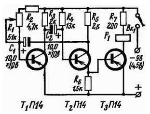
Amateur fishermen know that bass and other fish are more willing to take the bait, if the fishing line with a hook to impart oscillatory motion with a frequency of 200-300 fluctuations in minute. Such a bait is easy to make from regular fishing rods-tackle. The electric circuit of the rods is shown in Fig. 1. It consists of a multivibrator and power amplifier assembled on the transistor type A14. As the multivibrator is applied to the trigger with two unstable States" working in the key mode (transistors T1 and T2. The right shoulder trigger (T2) is also emitter follower. The oscillation frequency is governed by the resistance R1, the range of 50-250 oscillations per minute. The range of fluctuations can be changed the selection of values of capacitors (C1 and C2 or resistances R3, R4 and R5. The resistance R7 is used to limit the collector current of transistor T3 when the power structures from the battery voltage of 9V. When you use the source supply voltage 4.5 V resistance R7 should be excluded, and the remaining part of the scheme remain unchanged.

Fig. 1
As relay R1 is used, the relay RL-4 with a constant winding resistance current 200 Ohms. You can apply and relay of a different type with the resistance of the winding is not more than 500 Ohms, for example miniature relay type RES-9 or RES-10. The current response the relay should be no more than 30 mA. To anchor the relay is attached an elastic whip, which is used in conventional fishing rods-the coachmen.
The electronic part of the rod and the power source can be placed in her arm or in small box.
In design it is recommended to use transistors with gain current 20...40. Instead A14 you can use transistors type apparatus P15, p.
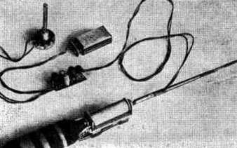
General view of the assembled fishing rod shown in Fig. 2.

Fig. 2
Properly collected electronic fishing rod, which consumes current not exceeding 30 mA.
Author: Yuri Victorov


