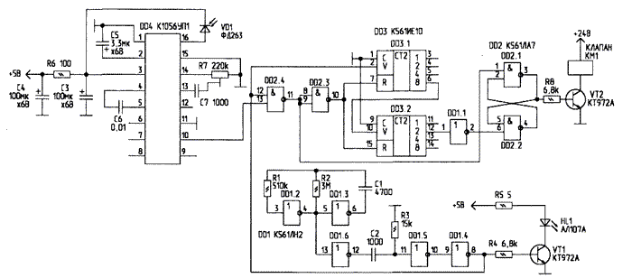
Permanent dorozhanie utilities forces us to seek new ways of saving water and electricity. We offer a photoelectronic device (Fig. 1) allows you to automate the process of washing and include water only in those moments when hands are under the faucet.

Fig. 1. A schematic diagram of a photoelectronic device
The device consists of a generator of short pulses on the elements DD1.2...DD1.6, key on the transistor VT1, the scheme of which is taken from [1], the photo sensor with amplifier on the chip DD4, counter delay DD3 and RS-flip-flop on DD2.1 and DD2.2.Short pulses are emitted IR LEDs HL1. When approaching the hand to the sensor, the reflected radiation is perceived by the photodiode VD1. The pulses are amplified by chip and DD4 output from the chip 10 are fed to the input 13 of the element DD2.4. The input 12 DD2.4 served with the clock pulse generator. When they match the output pulses DD4, exit 11 DD2.4 appears a logical "0" which switches RS-trigger on the elements DD2.1, DD2.2 in one state ("1" output 3). Then the VT2 transistor and turns on the solenoid valve for the water faucet KM1.
If the hands from the tap is removed, the output pulses with 10 DD4 terminated at the inputs R of counters DD3.1 and DD3.2 is set to "0" and, thus, permitted the operation of counters filling which pulses from the generator. As soon as the "1" appears at the output 12 DD3, RS-flip-flop is reset and the valve closes. The delay is done to ensure that the faucet does not turn off when short of stowing hand, for example, when washing your hair. This time can be increased if input 1 DD1.1 connect to pin 13 or 14 DD3, or reduced, by connecting the inlet to the outlet 6 (5) DD3. To clear the counters does not recommend, as without them the possible unstable operation of the solenoid valve.Place the device on a wall so that the valve reliably worked at putting the hands to the faucet and shut off when they are flushed. The sensitivity of the photosensor adjust trimpot resistor R7.

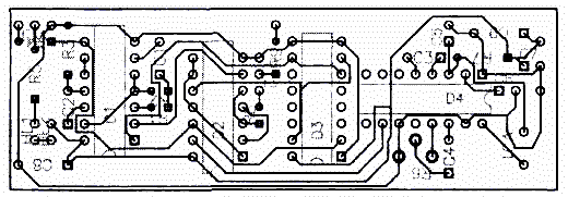
Fig. 2. PCB photomultiplier device
The device is going to single-sided PCB dimensions 28x84 mm (Fig. 2). IC DD4 and diode VD1 necessarily shield a thin metal sheet on both sides of the PCB.Literature
Author: S. Abramov, Orenburg, This email address is being protected from spambots. You must have JavaScript enabled to view it. ; Publication: www.cxem.net


