


")

It's nice in a dark frosty night to sit by the radiant heat of the fireplace. But it becomes even more comfortable when in it, like in a real fireplace, flickering "flame" and crackling logs. However, industrial design imitation firewood burning is weak, and all attempts to improve installed in them impeller foil give only a partial improvement of the result.
Tangible results can be achieved with the help of electronic devices, simulates the burning and crackling wood in the fireplace. The scheme is simple, performed on available components and can be easily repeated.
The device consists of a generator of white noise, amplifier, frequency divider, management node light sources of the simulator "cod" wood and PSU.
The generator of white noise, assembled on the transistor VT1, the resistors R1 - R6, the diode VD1, capacitors C1 - C3, generates a signal, the amplitude and frequency of which randomly changing. This signal is supplied to the level control (AC the resistor R7) and further to the terminals 12 and 13 of k176ie12 circuit. Feature the application of this IC is that its generating section functions amplifier audio frequency. On-chip amplified signal is supplied to the divider frequency every 256 pulses alternately switches the level a logic 1 on the outputs T1 - T4. The positive voltage pulses from the specified outputs through resistors R9 - R12 are received in the same sequence on control electrodes of the triacs VS1 - VS4, open them, leading to sequential ignition of lamps HL1 - HL4 installed in the fireplace for decorative panel with an image of wood. With DD1 pin 6 signal is supplied to simulator cod wood made on the VT2 transistor, resistors R13 - R15 and phone BF1.
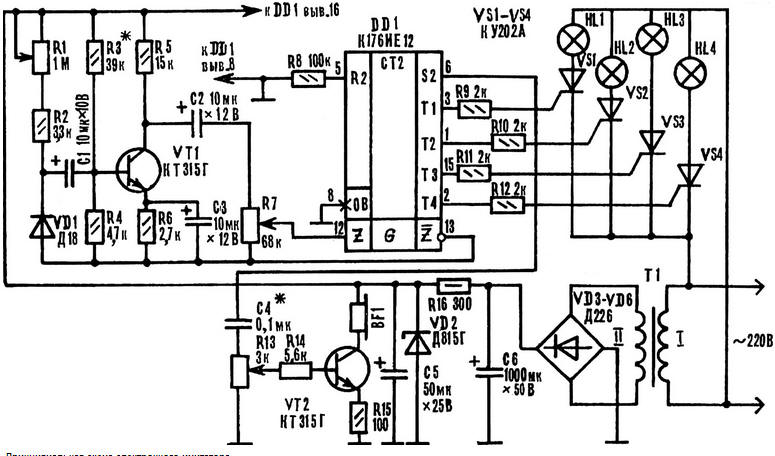
Schematic diagram of the electronic simulator
As as a reference for the chip selected signal, the amplitude and frequency which change randomly, and the frequency of the flickering lamps, and volume Petrucciani will also be constantly changing, creating the effect of "burning wood" the fireplace.
The power supply transformer T1, diodes VD3 - VD6, the Zener diode VD2, the capacitors C5, C6 and the resistor R16 is made according to the traditional scheme in the description not needed.
The simulator is assembled on a printed circuit Board size 112X92 mm, made of foil fiberglass thickness 1.5-2 mm.
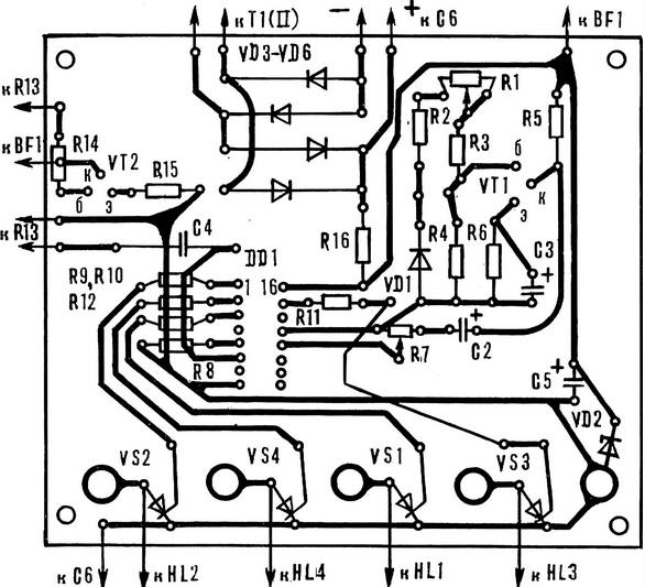
Circuit Board device circuit arrangement of elements
When handling the chip series C should take precautions the exception is exposure to static electricity. The soldering tip should to be connected to the common wire of the device and grounded. First fluster conclusion 7 IC, then 14, then the remaining findings.
Diodes: VD1 any of a series D2, D9, D18, VD3 - VD6 - any of a series D226. Triacs COOL, COOL, M or other, designed for switching voltage not lower than 300 V.
The resistors R1, R7 and R13 - JS4-1, R16 - MLT-0,5, the rest MLT-0,125. Capacitor C4 type CSR-2, the oxide can be K50-6, K53-1, K53-4 and others.
The power transformer is made on the yoke SH. The winding of I contains 4500 turns of PEV-1 to 0.05; II - 250 turns of PEV-1 to 0.23. Incandescent bulbs it is advisable to use low-power, such as 25 or 40 watts. Phone - impedance 50-200 Ohm (for example, TM-4, TDK-1).
Adjustment devices of the generator of white noise, characteristics which depend on the properties of germanium diode VD1. In parallel with the resistor R7 is connected piezoelectric phones or oscilloscope and serves the supply voltage. If the generator is not working, try to change the polarity of the diode, install the transistor with a large transmission coefficient current or to increase the supply voltage to 12 V (power supply unit replace the Zener DD). Further, the resistor R7 set the required signal level at the terminals 12 and 13 chip, achieving the desired frequency and the brightness of the flickering lamps. In the last turn set simulator "squid wood" by adjusting variable resistor R13 and choosing the value of capacitor C4.
Author: A. Charkin