In most home-made power supplies for aeroionizatora accent made for simplicity and cheapness of manufacture of the device from scrap materials. No operational facilities are not talking. The authors proposed article decided to Supplement traditional source microcontroller that allowed to diversify the modes of its work.
Under control of the microcontroller aeroionizator will be able to work not only in the usual continuous mode, although it provided the opportunity to regulate the supplied voltage on it. It will be switched on and off with specified period, and automatically stop working after a set time. The parameters for all the modes can be changed with the keypad, watching them the values on the led digital display.
The main part of the source schema (without plug to plug HER Board I/o) shown in Fig. 1.

There are three main functional site.
The node power - transformerless. This is justified when the total consumed from the mains current is not more than 15 mA. VD1 diode bridge rectifies the AC network voltage. Resistor R1 limits the amplitude of the pulses of the charging current capacitor C1. Rectified voltage through the quenching resistors R14 and R15 nourishes the final stage, the high voltage inverter is a field effect transistor VT4, and through resistors R2-R4 (falls approximately 70 V) - stabilizer voltage +12 V on the transistor VT1 for preliminary stages of the inverter. From voltage +12 V with integral stabilizer DA1 get +5V for the power circuits of the device.
The management node based on PIC16F628 microcontroller, which must be pre-programmed in accordance with the table. Data about established a user-mode source, the microcontroller stores in internal non-volatile memory. So there is no need, including ionizer, each time to set the source of his power re - work will be automatically resumed in the mode in effect at the time of deactivation.

(click to enlarge)
To proactively recognize this point, used two Comparators, embedded in the microcontroller. On their inputs (pins 1 and 18 DD1) arrives the voltage from the diagonal resistor bridge R18-R21, wherein during operation device the voltage at pin 18 DD1 is higher than its output 1. After disabling from the mains voltage at pin 18 DD1 quickly subsides, and the chain +5 BII and the output 1 DD1 some time remains almost unchanged due to the circuit VD3C7. Finding the potential difference of 18 conclusions and 1 changed the sign, the microcontroller manages to write to non-volatile memory data mode before the tension of his power will drop to a value insufficient to continue work.
The findings 10-13 microcontroller receives signals from four installed on motherboard I/o buttons, which control the source. Formed the microcontroller in serial form control signals are on the same Board with two digital led displays, the shift register DD2 converts to parallel form. Display dynamic: depending on the voltage levels on the pins 6 and 9 DD1 at each moment of time only one of the indicators.
High-voltage inverter constructed of transistors VT2-VT4 and pulse the transformer T1 is a string from small black and white TV. Rectangular pulses with frequency of 150...350 Hz generated the microcontroller DD1 at pin 8, enhance the transistors VT2 and VT3 to the amplitude 10..-12V. After shortening the differentiating circuit C8R13 these pulses open powerful CMOS transistor VT4, in the chain of flow which includes winding 5-7 the transformer T1. Diode VD4 - damping.
Pulses with increasing winding (9-11) of the transformer is fed to the rectifier multiplying the voltage on the diode pillars VD6-VD11. The structure of such the rectifier is well known. In its manufacture, you can use recommendations article V. duck "PSU "Chizhevsky" ("Radio", 1997, No. 10, pp. 42, 43).
Depending on the pulse repetition frequency of the voltage supplied to ionizer, changes in the range of 15...35 kV, if necessary, it can to increase, adding another several stages of voltage multiplication
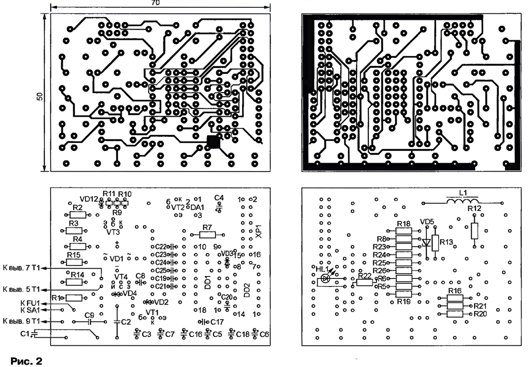
Main printed circuit Board of the source, which are almost all depicted in the diagram (see figure 1), the elements shown in Fig. 2. Fee - bilateral and details establish on both sides. Capacitors C2 and C9 - K73-17, and oxide - K50-35 or equivalent. The other capacitors (except C10-C15) - ceramic of any type.

(click to enlarge)
Transformer T1 with a high voltage rectifier and socket to connect XS1 the ionizer is located in a separate block. Capacitors C10-C15 - K73-13 or other for a voltage less than 10 kV. Protective resistor R17 must be able to withstand without breakdown between the findings of the full output voltage of the source. Resistors MLT-2 and similar only rated for 1200 V and no good here. Is suitable, for example, KEV-2. You can make a resistor R17 from a few less-high-voltage connecting them consistently.
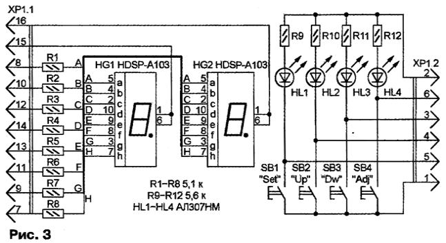
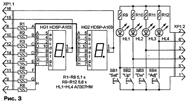
Board I/o assembled according to the scheme shown in Fig. 3 Press on any of buttons SB1-SB4 not only delivers the command to the microcontroller, but also includes the corresponding led HL1-HL4, giving the user the ability to visually to ensure that the team enjoyed. The resistors R1 - R8 limits the current element LEDs with a common cathode HG1 and HG2. When replacing indicators indicated on the diagram of the other type you may need to increase the brightness glow by reducing the nominal value of the mentioned resistors.

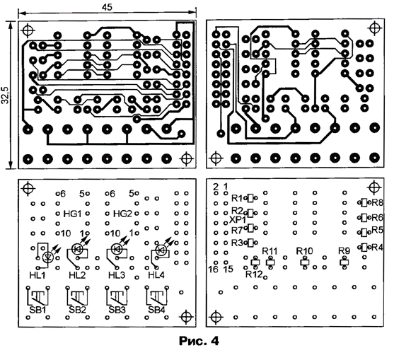
As main Board I/o bilateral. Drawings printed conductors and the layout of elements on both sides is shown in Fig. 4. Cost is attached to the front panel low-voltage unit so that the decimal point LEDs HG1 and HG2 on top (not the bottom, as usually). That is the position of the numbers on the indicators look right (this supported by the program of the microcontroller). Plug HR connect with the same name on main Board 16-wire ribbon cable.

The source starts to work in about three seconds after switching on the network and circuit switch SA1 (see Fig. 1). Displayed on digital indicators two-digit number - the value supplied to aeroionizator high voltage in kilovolts. It can be changed in steps of 1 kV using the SB2 buttons "Up" (up) and SB3 "Dw" (down). The condition of decimal points on the indicator shows which of the possible modes installed. Only six of them:
Lit decimal point on the display HG1. High voltage is produced continuously.
Lit decimal point on the display HG2. Cycle mode with a period of 1...10 min. In the first half cycle of the high voltage is, the second not.
Glow decimal point on both indicators. Similar to mode 1, but using preset time (1...99 min) high voltage is automatically turned off.
Flashing decimal point on the display HG1. The high voltage on the 1-enabled, on N off. The number N is set in the range from 3 to 10.
Flashing decimal point on the display HG2. The device operates as in mode 4, for a given time (1...99 min), after which a high voltage automatically turns off.
Flashing decimal point on both indicators. High voltage smoothly increases to maximum (35 kV), and then decreases continuously to a minimum (15 kV). The repetition period of the cycle - 5 min.
In modes 3 and 5 after a predetermined time, the control panel is "asleep" - high the voltage is turned off, the lights extinguished. Bring him out of this state clicking on any button, then the shutter speed will be repeated.
Switch modes by briefly pressing the button SB1 "Set" (set). The first one turns off the high voltage, and the digits on the display begin blinking, showing the current setting of the current mode, for example, the time during which the high voltage is turned on. The value can be changed by using buttons "Up" and "Dw". Subsequent clicks on the button "Set" switch modes with the corresponding state change decimal points. The numbers on the indicators stop flashing,and the new regime starts to operate, if hold the "Set" button pressed for longer than a second.
Button SB4 "Adj" (adjust) is intended for calibration - cast the output voltage in accordance with the indicator. Voltage measure the kilovoltmeter, connected between the socket XS1 and common wire. Can to use, for example, a microammeter with a current total deviation of 50 μa connecting it in series with the set of resistors for a total resistance of 1000 Megohms.
Before calibration it is recommended to install on the source indicators the minimum value of voltage (15 kV), although the procedure can be started at any. After pressing the "Adj" figures on the indicators will flash alternately signalling that the calibration mode is enabled. Operating with the buttons "Up" and "Dw", customize testimony kilovoltmeter to the value message to the indicators. Press the "Set" button. At this point, the microcontroller stores in non-volatile memory is needed to obtain a predetermined voltage value the frequency of the pulses and increases by 1 the number of indicators. Buttons "Up" and "Dw" once again regulate the output voltage and press the "Set" button. This procedure repeat as necessary. Exit the calibration mode by holding the button "Set" button for longer than a second.
Re-enable the source earlier than one minute after turning off should not be.
Authors: V. Sekriyeru, E. Munteanu, Chisinau, Moldova


