In the aquarium it is necessary to constantly maintain favorable for content fish temperature, luminance, saturation of water with oxygen. For this there are technical means - heater, illuminator, aerator. Manual management requires daily attention and direct involvement the owner of the aquarium. We offer our readers a machine will save him from many worries, taking over the management of lighting lamps, water heating, air supply and even once a day to give the inhabitants of the aquarium portion dry fodder. The device has long been used by the author and has been repeated radio Amateurs.
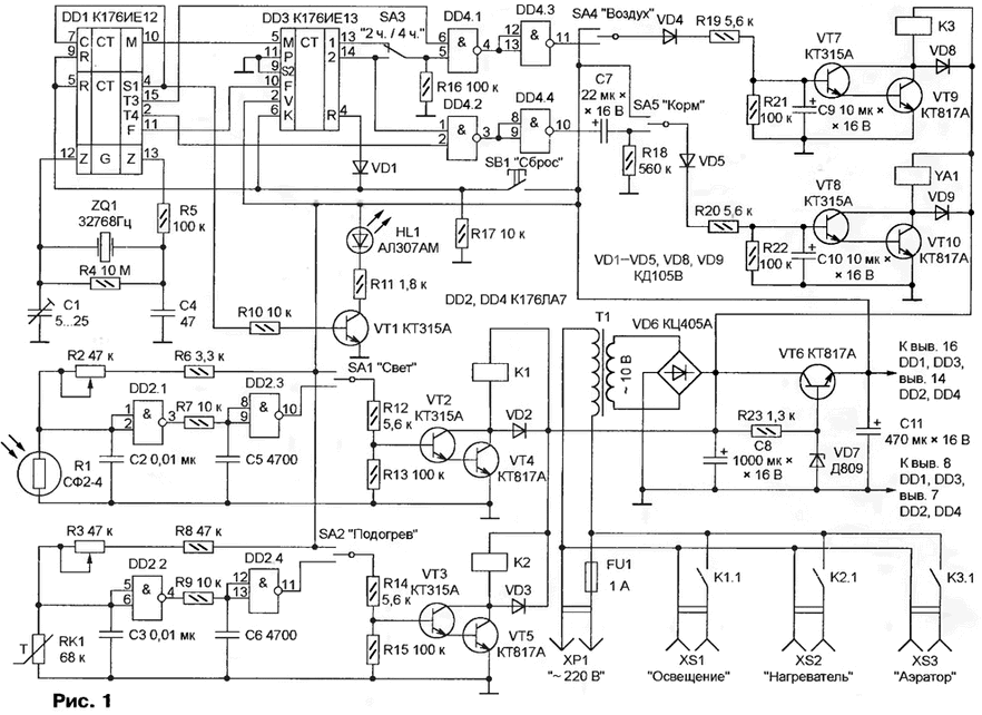
The scheme of automatic control of the aquarium shown in Fig. 1. It consists of a timer, who "manages" the work feeders and aerator (chip DD1, DD3 and DD4), heat stabilizer (DD2.2, DD2.4) and site lighting control (DD2.1, DD2.3). The timer turns the aerator at equal intervals of time with a period of 2 or 4 h, the feeder is triggered every 24 hours.

(click to enlarge)
When you press the SB1 "Reset" the counters circuits DD1 and DD3 come in initial state: at the conclusions of 13 and 14 DD3 and the outputs of the elements DD4.3 and DD4.4- low level. Transistors VT7-VT10 closed, relay coil short circuit and electromagnet feeders YA1 de-energized.
DD1 chip generates at its output M (pin 10) minute impulses who says the chip DD3. Depending on the position of the switch SA3 on the output element DD4.3 after 1 or 2 h at the same time pulses appear a frequency of 128 Hz. The voltage obtained by smoothing these pulses chain VD4R19R21C9, opens the transistors VT7 and VT9. This leads to the triggering relay circuit. The result is connected to the socket XS3 aerator works one hour from every two (or two hours out of four). This happens if the switch SA4 - at the bottom according to the scheme position. In the neutral position of the switch aerator off, top - all the time.
After 20 h after the installation of meters in their original condition, a pulse frequency of 128 Hz appear at the output of the element DD4.4. Begins charging the capacitor C7 the current flowing through the closed contacts of switch SA5, diode VD5, the resistor R20 and the sections of the base-emitter of transistors VT8 and VT10. Through the open the transistors and the coil of the electromagnet YA1 current flows. After approximately 5 s, when the capacitor C7 is fully charged, the transistors VT8 and VT10 is closed, current in the winding of the electromagnet is stopped. Next time the feeder will work in 24 h. If you want to submit the feed out of schedule, the switch short-SA5 transferred to upper circuit position, which causes the actuation of the electromagnet YA1.
Nodes of lighting control and thermal stabilization performed by the same schemes. The only difference in the type of sensitive element. In the first case it photoresistor R1, the second PTC resistor RK1. Therefore, we consider only the operation of the management node lighting.
As in the previous cases, automation works, if the switch SA1 is in lower according to the scheme position. In the neutral position, the lamp is turned off, the upper included constantly. When the illumination of the photoresistor R1 given above it the resistance and the voltage at the input of the element DD2.1 small, the logic level at the output of the element DD2.1 is high, the output DD2.3 - low, transistors VT2 and VT4 closed, relay K1 is de-energized, its contacts K1.1 are open. Lamps connected to the socket XS1, do not burn.
With the decrease in light resistance of the photoresistor R1 is growing. When reaching the voltage at the input of the element DD2.1 values, is equal to approximately half the supply voltage level at the output of the element DD2.1 becomes low, the output DD2.3 - high. As a result, the transistors VT2 and VT4 are opened, contacts relay K2.1 close the supply circuit of a light bulb. The variable resistor R2 adjust the threshold.
Because the illuminance changes relatively slowly, the element DD2.1 can long time to be in an unstable intermediate state, very sensitive to electromagnetic disturbances. For noise suppression capacitor C2 serve and chain R7C5.
The feeding unit of the machine consists of transformer T1, rectifier bridge and VD6 voltage stabilizer 8 In the Zener diode VD7 and the transistor VT6. Relay and the electromagnet feeders feed the unregulated 12 V directly from the rectifier.
Diodes VD2, VD3, VD8 and VD9 protect the transistors from voltage spikes emerging in tearing the chains of inductive loads and relay coils of the electromagnet.
In the machine used in the relay RAS passport 4.500.341 that you can replace other with the voltage not exceeding 12 V, operating current not exceeding 100 mA and powerful enough for switching a managed device contacts. Is mentioned in the scheme of the photoresistor SF to 4 suitable SF-1, SF-2, SF-9. Thermistor - MMT-4. Switches SA1, SA2, SA4, SA5 - three position P2T, moreover SA5 - preferably without fixation in upper circuit position. Overall the output of the transformer T1 is not less than 15 watts, the voltage of the secondary winding 10 of V.
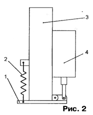
The design of the feeder shown in Fig. 2.

Plastic tube 3 internal diameter 26 and a length of 100 mm closed bottom flap 1 and filled with dry food for fishes. Under the action of the electromagnet 4, the valve 1 is opened and the aquarium comes food. After turning off the current of the coil spring 2 moves the damper back to the original position. The stroke of the armature of the electromagnet should be 4...8 mm. In copyright the instance used the drive unit of hitchhiking cassette recorder "IZH-303-Stereo". At a voltage of 12 V it consumes approximately 500 mA.
The heating element is made of ten series-connected resistors MLT-2 value of 150 Ohms. Resistors placed in a glass or ceramic tube inner diameter 16 and a length of 300 mm, filled with dry sand and sealed on both sides with rubber stoppers or compound. Through one of the tubes omitted insulated connecting wire. Power this heater is 32 watts is sufficient for an aquarium with a volume of 30 L. Thanks good dissipation of heat, the temperature regime dvuhletnih resistors remains valid. If the volume of the tank is greater than or less than the specified, power the heater will change accordingly.
The thermistor RK1 similar in a sealed tube placed in an aquarium the maximum distance from the heater. Photoresistor R1 is mounted in such a way that the illumination did not change with turning on and off lamps, covering the aquarium.
After switching on the machine to the network blinking with a frequency of 1 Hz led HL1 demonstrates the correct operation of the chip DD1. If the flashing is missing, probably not excited by the generator on the quartz resonator ZQ1. Sustainable generation accomplish by rotating the rotor of the tuning capacitor C1.
The nodes control the aerator and check the feeder, temporarily breaking the circuit, connects pin 10 of the chip with DD1 DD3 pin 5, and filing for the latter instead minute-second pulses with output 4 DD1. As a result, the operation of the machine will accelerate to 60 times, the aerator will be switched on and off using one or two minutes and the feeder after 24 minutes When needed, selecting the capacitor C7, achieve the desired duration of inclusion of the electromagnet feeders.
Establishing the temperature controllers and the illumination of the aquarium, variables resistors R2 and R3 set the required thresholds. If the change intervals thresholds is insufficient, replace the resistor R6 or R8. The axis of the variable resistor R3 can be provided with a scale graduated in values of temperature. Graduation produce, by placing the heater and thermistor in a separate container, filled with water.
Literature
Author: A. Dubrovsky


