


")

It is known that even a small layer of ice on the evaporator of the refrigerator is substantially degrades its performance. It is therefore recommended may often include activatel. It was established experimentally that for commercial refrigeration systems optimal it is possible to consider a mode of operation in which 2…3 h and cooling 10…20 min - thawing. It is this mode provides the attention readers device. It can be used in refrigerators with separate compressor and heating element of activates.
Electronic automatic temperature control work the refrigerator consists of a temperature-controlled [1] and specifies the time [2] nodes. The first one measures the temperature in the chamber of the refrigerator and maintains its specified by the regulator within, and the second periodically every 2…3 h on 10…20 min includes a heating element of activates of frost.
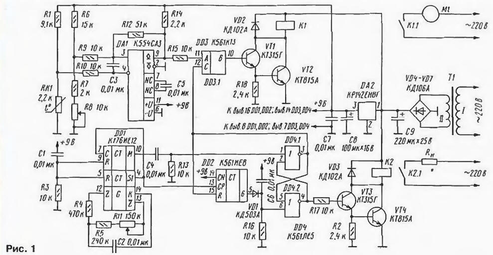
Schematic diagram of the device for the temperature control of the refrigerator it is shown in Fig. 1.
(click to enlarge)
The thermostatic unit is composed of a comparator on the chip DA1, measuring bridge R1, R6 - R8, RK1, device lock controller on the chip DD3, the current amplifier transistors VT1, VT2 and the electromagnetic relay K1, which includes the compressor motor of the refrigerator. The thermistor RK1 performs the functions the temperature sensor.
When the thermostat compares the voltage on the shoulders measuring bridge. The signal appearing on its diagonal, is fed to the inputs of the comparator DA1, and with its output via the node lock on the chip DD3 - current amplifier for transistors VT1 and VT2, the burden of which serves as an electromagnetic relay K1. When the temperature inside the chamber of the refrigerator exceeds the threshold set variable resistor R8, the output of the comparator DA1 will be high voltage the level that will pave the transistors VT1 and VT2. As a result, through the winding turnips K1 current flows. it works and its contacts K1.1 connect the motor M1 compressor to the network. The temperature in the refrigerator will start to decrease, and the resistance of the thermistor RK1 to increase. But as soon as the temperature decreases to the threshold set by resistor R8 with consideration of hysteresis, insertion resistor R12, will trigger the comparator DA1 and its output is set the low voltage level. Transistors VT1 and VT2 of the current amplifier is closed, the current through the relay coil K1 will cease and the contacts K1.1 open the power circuit compressor motor.
The timing unit is composed of a timer [2] on chips DD1, DD2, RS-flip-flop on the elements of DD4.1 and DD4.2, the current amplifier transistors VT3, VT4 and electromagnetic relay K2 that controls the heating element activates freezer. DD1 chip performs the functions of defining generator and frequency divider by 32768 and 60 and the chip DD2 - counter-frequency divider 6.
When the power voltage supplied to the inputs R of the chip through DD1 reset circuit C1R3, install it in the zero state. Accordingly, the voltage power passed to the input of the element DD4.2 RS-flip-flop through a reset circuit C6R16, translate it in one state. As a result, the output 4 of the element DD4.2 and on a 2 element DD4.1 set the low voltage level, and the output 3 element DD4.1 - high. The last will go to the reset input R of the counter-divider DD2 and will reset it.
The master oscillator DD1 chip produces a pulsed voltage, frequency which is set by the variable resistor R11 in the range of 175…280 Hz. The period of this tension in the middle position of the slider of the resistor R1 is 1 approximately 4.6 MS. In DD1 chip pulses her master oscillator fed to the frequency divider, which increases the period of the pulse voltage to 32768 times, and the output S1 is a signal with a period of oscillation Further 2.5 min. the signal is input With DD1 chip, and its frequency is divided into 60. so the pulse period of the output voltage M of the chip DD1 will be 2.5 hours The first positive differential voltage appearing at the output M of the chip DD1 approximately after 1.5 h, passes through the differentiating circuit C4R13 on input 1 element DD4.1 RS-flip-flop. The trigger switches and the voltage on output 3 element DD4.1 changes from high level to low. In the end, the output element DD4.2 and, accordingly, the input element DD4.1 set voltage high level. It will pave the transistors VT3, VT4, through the relay coil K2 will flow current, the relay will go off and closed contacts of K2.1 connect the heating the element of activates Rh to mains.
Simultaneously, the voltage of low level from the output of the element DD4.1 is input to the permission From the switch on the chip DD3. The switch is closed and disconnects the thermostat from the current amplifier.
It's a low voltage level applied to the input R of the chip DD2, allows the operation of the frequency divider 6. As a result, the output signal S1 of the chip DD1, input CP chip DD2, cause after 15 min the appearance at its output 6 (pin 5) high level of signal. This voltage is fed to the input 6 element DD4.2 RS-flip-flop. The trigger switch, and the output (pin. 4) item DD4.2 will be a low voltage, which will close the transistors VT3 and VT4. The passage of current through the relay K2 will stop, and the contacts of K2.1 disable the heating element of activates from the mains. The signal arriving at the enable input chip DD3, will open the switch and the thermostat will be connected to the current amplifier. Divisors on chips DDT and DD2 will be in nil and RS-flip-flop - in a single state.
With the arrival of the next pulse from the output of the M circuits DD1, after 2.5 h. activatel again switch on for a time equal to 15 minutes.
The power supply device for the temperature control of the refrigerator consists of transformer T1, bridge rectifier diode VD4 - VQ7. stabilizer the voltage on the chip of DA2 and smoothing capacitors C7 - C9. Output voltage supply +V. 9
All of the elements of the device, except the transformer T1, is mounted on a circuit Board from unilateral Folle-giovannoli fiberglass thickness of 1.5 mm and dimensions 110x65 mm (Fig. 2).
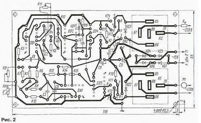
Used for mounting fixed resistors MLT-0,125, variables (R8 and R11)-JS4-1, a thermistor RK1 - MMT-1. Capacitors C8 and C9 - C50-16, C1-C7 - K73-9. Transistors CTG (VT1, VT3) can be replaced by CTA and CTA (VT2, VT4) - CTA. Electromagnetic relays - automotive 113.3747-10 [3], powerful contacts withstand the motor of the compressor of the refrigerator. The transformer T1 with a capacity of 2…4 W - AC adapter [4].
When establishing the control device is disconnected from the refrigerator, and instead of compressor motor and the heating element of activates connect the table lamp.
Thermostatic Assembly operates when the temperature changes from -14 to +4°C, therefore, at the time of its establishment, it is recommended to reduce the resistance of the resistor R8 to 1.5 ohms, a R7 - close jumper. In this case, the thermostat will to operate in temperatures from +18°C to +40°C, which is easy to achieve when adjustment.
To accelerate test the operation of the timing node capacity the capacitor C2 to reduce 100 times. then the period of the pulse voltage the output M of the chip DD1 will be reduced to 90 C. Checked and adjusted the unit can be placed in the refrigerator, do not forget to increase the values of elements R8, C2 to indicated in drawings.
Chip DD3 can be avoided if the right circuit output resistor R15 to connect to the base of transistor VT1 and the point of its connection through the diode KDA to connect the output 3 DD4.1 (cathode of the diode is to this output).
Literature
Author: G. Skobelev, Kurgan