


")

Automatic device allowing to control the level of water in immediately two locations - at its source (the well) and in the receiving tank, was described in the magazine "Radio" (1998), No. 5, pp. 45, 46). To work required four sensors, a New version of this machine has only two sensors.
Managed to do it by modifying the algorithm: instead of hysteresis on water levels in containers use the time delay the pump after it off.
Diagram of the modified portion of the machine shown in the figure.
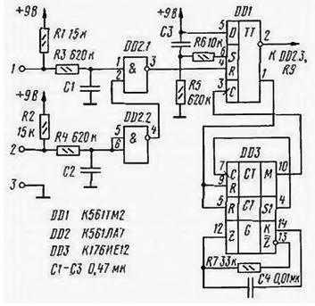
To pin 1 connected a sensor mounted in the receiving tank at the maximum allowable level water, and to pin 2 of the sensor located in the well at a minimum. Device works well.
When the power of the differentiating chain C3R5 produces short the pulse received at the input S of the trigger DD1. Regardless of the voltages on other the inputs on the direct output 1 of the flip-flop appears at the level of the log. 1, establish counters chip DD3 in the zero state.
The voltage on the inverted output trigger 2 DDI, manages the pump operation, and further the behavior of the device are determined by the water levels in the well and receiving the tank. If in the moment of switching on the pump the water level in the well exceeds minimal, and the receiving tank is not full, both the inputs of the element DD2.1 high logic level is present, the input R of the flip-flop DD1 is low. After the initial momentum of the installation, the trigger will remain in a single state. The voltage log. 0 with its inverted output includes the pump motor. The counters of the chip DD3 inhibited by the signal log. 1 arriving at their inputs with R direct output of the trigger DD1.
Once the receiving tank is filled or the water in the well drops below acceptable level, the input R of the trigger of DDI postulat the level of the log. 1, the trigger switches to the zero state. The pump switches off, and the log. 0 with direct access DDI will allow the counters of the chip. The frequency of master oscillator on the elements of the chip DD3, R7. C4 is 2100 Hz, so after 32768x39/2100=608 C (about 10 min) [1] at the output M of the chip DD3 appears a positive voltage drop. If at this point the conditions of the pump will be performed, the input R of the flip-flop DD1 will log. 0 and because the input D is high. 1, he'll move to one state and the pump turns on. If at this point run the pump is not necessary, the trigger DD1 will remain in the zero state.
The next attempt of inclusion will happen after a full period of oscillation at the output M chip DD3, i.e. after 32768x60/2100=936 (about 15 min). Attempts will be repeated every 15 min until the conditions of the pump.
If at the time of power-up conditions the pump will not be executed the voltage on the inverted output 2 trigger DD1 will remain high, the pump is not turns on. The first attempt of its inclusion will occur after 10 min, the rest every 15 min.
In establishing the device is almost not needed, if you wish, you can install the rhythm of his work, counting respectively the values of the elements R7 and C4.
As circuits DD1 and DD2 can be used other suitable apparatus series CMOS, and DD3 - set CIE. CIE. In the latter case the frequency of the master oscillator should be about 50 Hz.
For the same purpose it is well suited chip CRES [2. 3). Unused the inputs of the circuits should be connected with the common wire or the positive wire power. The last recommendation does not apply to the chip CRES. since it contains resistors, grounding all inputs.
Literature
Author: S. Biryukov