


")

The light switches in hallways and corridors of our apartments are usually located near the front door, it is the fact that, upon entering the apartment, you can immediately turn on the light. But often the majority of the time the light in the hallway is lit for hours useless because it has no Windows and lamps and include in the daytime, forgetting to turn off. To conserve power switch in the hallway, it is advisable to equip a simple device that will automatically switch the lights off after a preset time interval. The device allows you to work with the so-called "energy saving" fluorescent lamps, and lighting you can use a standard switch to trigger at a specified time, but in any time off.
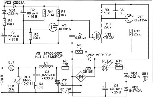
When the device is plugged in, but the lighting is not enabled, the capacitor C5 is charged to a voltage stabilizing Zener diode VD5 (about 10). Since the capacitor C4 at this time discharged, and field-effect transistor VT2 is closed, also closed the transistor VT3, low-power SCR VS2 and powerful triac VS1. Through HL1 led illumination button SB1, the current flows around 0.8 mA, limited by resistor R11. If the backlight is not needed, the led can be deleted and replaced by a jumper. If a short press on the button, SB 1, the capacitor C2 charges to a voltage of about 9 V, through a resistor R5 to charge and the capacitor C4. The voltage between the gate and the source of transistor VT2 exceeds the threshold that will lead to the opening of the transistors VT2 and VT3. As a result open SCR VS2 and triac VS1. When you turn on the proposed scheme and used as EL1 incandescent lamp triac VS1 is coming off at an instantaneous value of the mains voltage to about 10 V, so the level generated by the device noise is negligible. In this case, the noise filter L1C3R3 is not necessary, although very desirable.
The situation with the network filter is replaced by the opposite, if EL1 - "energy saving" fluorescent lamp with electronic ballast. The level of interference generated by the device will be more. It should also be noted that most of the "energy saving" lamps are intense sources of radio interference. To reduce interference as the regulator, and a lamp, in series with the first to establish the second link LC filter. If the lamp with electronic ballast, being turned off, occasionally erupts, parallel to it, you can include a resistor of 68 ohms and a power of 2 watts. This resistor significantly reduces and the intensity of the interference. The time during which the lamp remains on, mainly depends on the resistance of the resistor R4, the capacitance of the capacitor C2 and the threshold voltage of the FET VT2. Once voltage gate-source will be less than 1.2…2.5 V, the transistor VT2 is closed, simultaneously with VT3 is closed, will not open VS1, VS2, the lamp will be de-energized. To extinguish the light before the expiry of the exposure, press and about 5 to hold down the button SB1 until the light goes out. During this time, the capacitor C1 is charged through the diode VD1 and the resistor R1 to a voltage higher than the threshold VT1 transistor opens and discharges the capacitors C2 and C4. Re-enabling the illumination is only possible after 5…8 S. Varistor RU1 protects your device from surge voltage. The capacitor C6 eliminates false positives. The inductor L1 is wound a wire PEV-2 in diameter of 0.35 0.51 mm…150 turns on the ferrite ring 2000NM1 size CHH.
You can try to use the filter choke from a defective fluorescent lamp or one of the correction coils from domestic color TV USCT. Triac VT-600C can be replaced MAC8N, BTA06-600SW or others with a valid voltage is not less than 600 V and a direct current of about 4 A. It is desirable to set on aluminum or copper telliott size 50x15x1 mm. With this performance the power unit the device can operate with loads up to 350 watts. SCR MCR100-6 can be replaced MCR100-8, P0102DA1AA3. Instead of the transistor KTA you can use the import 2SA1625K-2SA1625M or MPSA92. High-voltage field-effect transistor CPA can be replaced BSS124. Instead of the transistor KPA suitable CPB, CPV, CPA, CPA, BSS88, ZVN2120. It is desirable that the transistor VT1 had a smaller threshold voltage than VT2. Usually transistors KB, KV open at a lower voltage than CPA. Diode bridge DB105 will replace RB154-RB157, CCA, you can make a bridge of four diodes 1N4004-1N4007, CDG-KD243ZH. Instead KDE you can use any low-power silicon diodes, e.g. 1N4148, CDA.
Is mentioned in the scheme of 1N4740A Zener diode other suitable low-voltage stabilization 10 V. the Led can be set to any of the series AL307, CIPD, CIPD. Capacitor Sz - K73-17 or K73-24V rated voltage 630 V. the Oxide capacitor C2 should have a possibly smaller leakage current, the author used tantalum K53-18. In the absence of a suitable tantalum or niobium capacitor you can try to install the import of aluminum oxide on the operating voltage of 35…63 V. the Varistor FNR-10K431 you can replace FNR-14K431, FNR-20K431, FNR-20K471 or other classification voltage 430 or 470 V. When using low-capacity varistor, for example, FNR-05K471 it is desirable to connect a resistor of 100 Ohms and a power of 0.5 W in parallel to the diode bridge VD3 - to the right (the scheme), the findings of the resistors R6 and R7. Resistors R3, R6 and R7 may want to bring a non-combustible P1-7 or similar import. Usually, these resistors are painted in a light gray-blue color. The remaining resistors - General purpose of any type.
The device is mounted in a wall box for switch wiring hidden on the Board with a diameter of 65 mm. the switch is used as the button SB1. For this purpose, under its key set spring that returns it to its original position after pressing. To isolate the circuit from the metal box installation it is desirable to use a non-combustible material, such as a thin glass fiber with foil. In any case, do not wrap the tape device. With the resistor R4 and the capacitor C2 indicated in the diagram of the values after short pressing the button SB1, the lamp illuminates for approximately 25 minutes, These elements can be selected to obtain the desired duration of the glow.
When managing multiple connected in parallel "energy saving" lamps with a total power up to 100 W in series with them it is recommended to turn wirewound resistor 4,7 6,8…Ohms and a capacity of not less than 7.5 watts. It will limit the amplitude of the inrush current that occurs in moments on these lamps. As the resistor heats up, do not mount it in an enclosed space, including the installation box. The described device can be used to limit the time of inclusion not only of lamps and other electrical appliances.
Author: A. Butov, S. CORBA Yaroslavl region; Publication: www.cxem.net