Measurement of depth of dredged or - search for sunken objects is possible by using an ultrasonic depth gauge, diagram and a brief description of which is given below.
The principle of operation is based on the reflection of short ultrasonic pulses from a river or seabed. This is not measured by the travel time of the pulses in the water column (the speed of sound in water of 1500 m/sec), and the number of reflections per unit time pulses. The depth of penetration of the ultrasonic pulses is determined by the radiated power and sensitivity of the receptor. In the described device, it does not exceed 20 m.

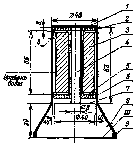
Fig.1
Depth gauge consists of two parts: a magnetostrictive sensor and electronic unit. Magnetostrictive sensor (the device shown in Fig. 1) is a Nickel rod 4 is fixed with the copper ring 1 in the housing 2. The rod is covered with a frame 5 with a wound on his coils 3, sealed cork lining 6. Ultrasonic vibrations (their maximum amplitude at resonance frequencies) of the Nickel stem and plate 7 are transferred to the aquatic environment. To exclude the fluctuations of the water level in the sensor socket, it is closed by a rubber membrane Yoo thickness 0.5-0.8 mm, which is held by the brace 9. When measuring through the hole 8 into the socket is filled with water.
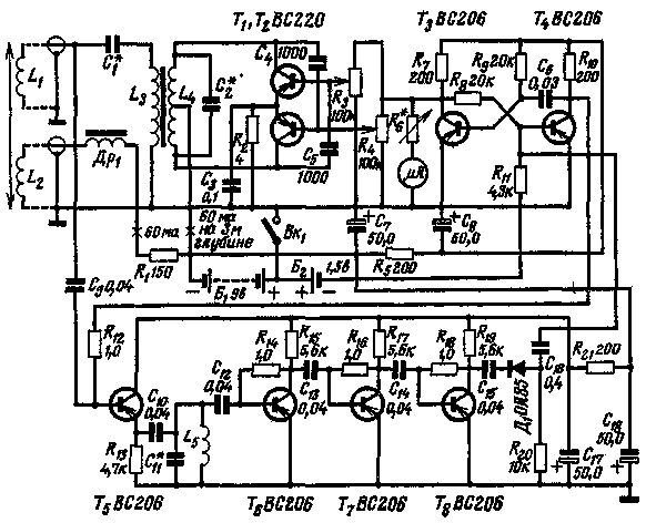
The electronic unit (Fig. 2) consists of an ultrasonic generator, assembled on the transistors T1, T2, modulator transistors T3, T4, receiver of the reflected pulses T5-T8 and a dial indicator with a scale calibrated in meters.

Fig.2
Two-stroke generator with capacitive feedback generates ultrasonic vibrations of a frequency of 40 kHz. The load of the generator is the circuit formed by the coil L4 (she wound on a closed ferrite core section 2 cm2) and a capacitor C2. The specific data of these quantities in the original is not reproduced. They are chosen on the basis of measured (a known manner) the inductance of the exciting winding L1 of the vibrator (with 1500 turns of PEL 0,35), which in turn depends heavily on the quality core of the vibrator. In atom, it should be borne in mind that the inductance L1 and the capacitor C1 form a series resonant circuit, agreeing with the circuit of the generator is performed using the coil L3 communications, the Number of coils L3 are also found empirically. Coil L2 bias has 3000 turns of wire PEL of 0.15, the value of its induction of 0.5 T. in series with L2 is a choke DR1 preventing the penetration of vibrations of ultrasonic frequency in the circuit bias. The value of inductance of 0.25-0.3 MT.
Multivibrator (transistors T3, E4) is used in the device as a modulator and frequency meter. The time constant of its base circuit 600 us. With the collector of T3 are removed negative pulses controlling the operation of the ultrasonic generator. The required voltage of the pulses are set variable resistors R3, R4. In this circuit a DC voltmeter with a threshold value of 10, which measures the average voltage of Nicolson. In addition, flip-flop circuit together with the transistor T5, performs the functions of the electronic switch, closing the input of the receiver at the time of sending the probe pulse and opening it at the reception of the reflected pulse.
The structure of the receiver amplifier includes transistors T6-T8 and the detector diode D1 Reflected pulses taken by the sensor (using the inverse Magnetostrictive effect), enhanced three-stage amplifier, the input of which includes a selective circuit tuned to a frequency of 40 kHz, are detected and through a capacitor C16 is received in the base circuit of the transistor T4, starting the multivibrator. Since the number of reflections per unit time of the pulse depends on the depth, changing the past changes the start frequency of the multivibrator.
Initial calibration of the device is produced at a known depth is 3 m. the Vibrator is immersed in water and variable resistors R4 R6" set the current consumed by the generator is equal to 60 mA, the voltmeter Reading when calibrated at 3 m. the Amount of current consumed by the generator, should decrease with increasing depth. Maximum depth will correspond to the minimum deflection of the depth gauge.
Literature
"Radioamater", 1970, N5.
Publication: N. Bolshakov, rf.atnn.ru


