Some products are powered by three-phase network, especially those in composed of three-phase motors require the right phase sequence: the phase voltage must lag behind the voltage phase And 120°, and the voltage phase should lag behind the voltage phase by 120°.
When an incorrect phase sequence is enabled, the motor will rotate in return the correct direction. This will lead to the deterioration of its cooling, if it is provided with an impeller, and in some cases, when the shaft motor connected to a gear transmission with ratchet, very the likely failure mechanism. In industrial halls is provided by three-phase powered with the correct phase sequence. In rural areas, the consumer filed only two of the phase voltages or the phase and zero, and all three phases fail only when needed. In these cases, you should verify the accuracy of the phase rotation, and the phase display can help.
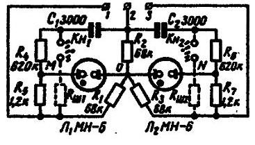
Schematic diagram of the pointer shown in the figure.

Terminals 1, 2 and 3, the pointer is connected to three-phase network. The schema contains two neon lamps, which are served voltage of the two phases relative to the third using phase-shifting chains C1, R4 and C2, R6. The resistors are the same resistance R1, R2 and R3 are designed to create artificial point zero.
In case of correct phase sequence of the voltages connected to the terminals, lights L1 lamp, and the lamp L2 is not on. If an incorrect sequence, on the contrary, the lamp L2, and L1 does not light. In this case you need to swap any two phase wires. If both lamps light up, this indicates breakage of one of the phases, but if none of the lamps are, therefore, two phases are broken out of the three.
Dual button KN, KN and resistors Rml and Rm2 shown in the diagram dashed lines are used to using pointer in case of three phase voltage frequency of 400 Hz. If such control is not expected that these elements can from the diagram to be deleted.


