


")

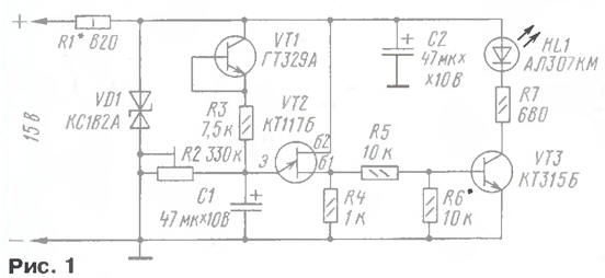
In most improvised devices with powerful transistors no heat protection. And the information about the thermal regime of electric motors, power transformers (especially welding) is also required. It will give a device, scheme which is shown in Fig. 1. Controls the temperature of the sensor on germanium transistor VT1. It is connected to the generator performed on the transistor VT2. With generator output signal is supplied to the amplifier (transistor VT3) loaded on led HL1.
While the case temperature of the transistor-sensor does not exceed 60 °C, led HL1 is not lit. At a temperature of about 70 °C, the led flashes with a frequency of several times per minute. If the temperature gauge rises to 85…105°C, the led flashes with a frequency of 2…3 Hz. The frequency of outbreaks can to judge the degree of heating of the controlled object.
The choice of the germanium transistor as the temperature sensor caused by what reverse collector current with increasing temperature increases dramatically when a temperature of over 70 °C.
In the device used fixed resistors MLT, S2-23 defined in the diagram power trimmer resistor R2 may be SDR-38A, RP1-63M or another small-sized. Oxide capacitors - K50-16, K50-35. The Zener diode VD1 - any low-power voltage of 7…9 V, for example, also mentioned in the scheme, CSA, XI, XA, XA, CA, DB. Led - any of the series AL307, CIPD, CIPD preferably red glow.
As a sensor used transistor series GT because it is one of the few germanium transistors, which have a version in a plastic casing that greatly facilitates the installation on the controlled surface. Instead you can use transistors series MP - MP, but then will need the insulating gasket. In place VT2 may be possible to apply any unijunction the transistor of the series. Transistor KT315B replace any of the series KT315, CT.
The indicator can be powered with any voltage from 9 to 18 V. the Selection of resistor R1 set power consumption 8…10 mA. At a voltage of 10 In R1 can have a resistance of 220 Ohms At 24V - 1.8 kOhm.
When creating a device temporarily exclude the transistor VT1 and install instead, the resistor 33 kOhm. The selection of resistor R6 achieve reliable extinction of the led in the pauses between the flashes. After that, connect the temperature sensor. A trimming resistor R2 regulates the sensitivity of the indicator. It is recommended to be set such that the led began to occasionally erupt at a temperature of 65…75 °C.
Transistor series GT in a plastic housing fixed to a controlled the special grooved surface of the petals, used to install on the transistors heat sinks series CT, CT and the like.
If the temperature sensor will be used a germanium transistor in metal case, it is necessary to use a thin insulating gasket mica or Teflon. It is also desirable to use heat-conducting paste CBT 8.
The lower limit of sensitivity of the indicator is about 50 °C. If, in rare cases, the sensitivity must be increased, in parallel to the transistor VT1 should to connect 1-3 of the same transistors.
Author: A. Butov, S. CORBA Yaroslavl region