


")

The proposed device is designed for remote measurement of level liquid (water) in the tank, for example, the water tower. The scheme controls up to 4 intermediate values of the levels. Liquid, in principle. maybe not conductive. In this case, as sensors reed switches are used For water you can take as reed switches. and contact sensors (pins) made of stainless steel.
Water (conductive liquid), filling the tank, alternately connects the electrodes with the common wire is connected to the bottom electrode.
In the case of the use of reed switches are located inside the tank floats on which fixed magnets. When the level of liquid floats together with magnets lifted, and the switch is alternately opened.
The scheme is physically divided into two parts transmitter and receiver. For transmission data we use two-wire line with length up to 10 km from the transmitter applies pulse width modulation signal (PWM) Thanks the device is efficient when the parameters of a connecting line in wide limits and does not require constant adjustment. Structural scheme the device shown in Fig.1.
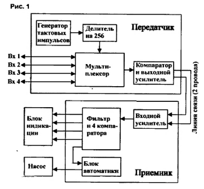
The transmitter (Fig.2).
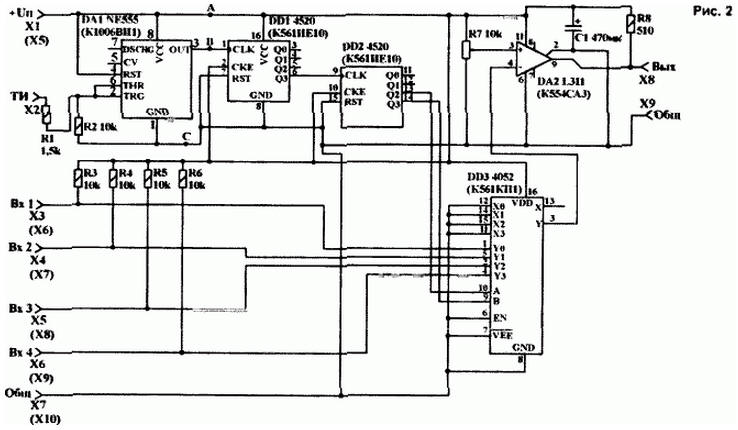
The clock pulses are received from the network. To do this in standard AC adapter diode is added (enables the anode to the diode bridge, and the cathode to a smoothing capacitor) Timer DA1 is used to increase toughness the fronts of the clock pulses and to increase the noise immunity of the timing generated by the timer the pulses arrive at the input 2-cascaded frequency divider DD1. DD2. With outputs the divider pulses pogutse the address inputs of the multiplexer and cyclically D03 connect the inputs Y0…Y3 DD3 output Y. the Inputs of the multiplexer are connected to sensors.
Block of reed sensors are made according to the scheme in Fig.3
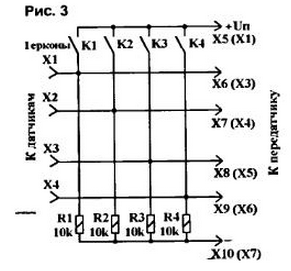
Thus, each of 4 sensors allotted equal time on the survey i.e., the data (voltage levels) in these moments are part of the output DD3 (Fig.2) and further, the inverting input of the comparator DA2. The second comparator input (non-inverting) connected to a variable resistor R7 Comparator compares the voltage levels on inputs, and, if the voltage at the inverting input becomes smaller (sensor closed water or trigger the reed switch). in DA2 there is a high level. Resistor R7 to adjust the sensitivity depending on humidity, insulation resistance and water. When using reed switches engine R7 set approximately midway In principle. R7 is possible in this case to replace the two resistors of the same resistance (5,1....18 kOhm)
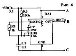
With the comparator output signal goes to the connector. Common wire is "-" power. Since the comparator output is open collector, you need "pull-up" resistor R8. Not to "mess" with the clock pulses from network, timer DA1 can be translated in a mode of self.
The scheme of inclusion in DA1 this case is shown in Fig.4.
The receiver (Fig.5).
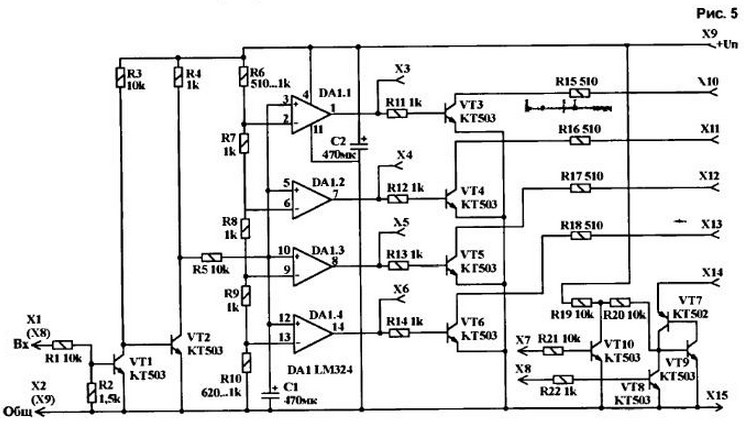
At the receiver input is the divider R1-R2, which increases the immunity of the device. The input key on the VT1 transistor inverts input signals with a level below 4…5 are ignored. The second cascade on VT2 once again inverts the signal. Next, the signal is sent to pulse width Converter time-voltage elements R5-C1. Full charging of this capacitance occurs 6…10 seconds.
Performance is determined by the rate of filling of the tank. The assembled chip DA1 the comparator 4 levels. The switching levels are set by resistors R6. R10 With the outputs of the Comparators control voltage is fed to the base key transistors ..VT3 VT6. which commutate the LEDs. Resistors R15 R18.. in the collector circuit of rated current of 15 mA with voltage 12 V. This current is sufficient for SuperBright LEDs in the led are the anodes, they are connected to "+" supply.
For automatic control of the pump I used the analog lockable thyristor transistors VT7 VT10.... Input X7 is connected to the output (XS…X6). appropriate the level at which you want to enable the "thyristor" (when a "0" on the desired output), and input X8 - the level at which you want to turn it off (when "G at the output). To the output x14 you can connect the actuator of the pump (switching current 300 mA or relay, and his contacts - powerful starter.
Powered receiver and transmitter - local (6.15 In). The current consumption of the receiver 10.. 80 mA, the transmitter - 7… 30 mA.
When setting up the transmitter on all the inputs of the sensors serves zero potential (simulation of a full tank) At the output of the transmitter should be close to supply voltage. Connecting one sensor to the minus (remaining in the air), monitor the presence at the output of the transmitter quarters of voltage power.
Tuning of the receiver is reduced to the selection of resistors R6… R10, specifying levels of response. At the time of setting the resistors R6 and R10 are replaced variable resistance 1…3.3 K Ohm. Resistor R6 achieve sustainable burning all 4 LEDs at full tank, R10 - sustained burning 1 LEDs on one sensor, enclosed in a minus.
Author: V. Ponytail, S. Caredarovka Kharkiv region.