The device is designed to control conductor flowing through him alternating current. The sensitivity of the device is such that allows contactless the way to control the conductors with a current of 250 mA or more.
In Fig. 1 shows a circuit diagram of the device.

(click to enlarge)
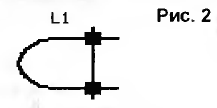
Sensor alternating electric current with a frequency of the mains (50 Hz) is the inductor L1. L1 is made in the form of a U-shaped core 2.5 cm in diameter, which is wound with 800 turns of wire of magnetic material with a diameter of 0.15...0.25 mm (Fig. 2).

The core of the coil can be taken from the Central part of the interstage or matching transformers bass, or small-sized electromagnetic calls. The main requirement for the core - wound coil L1 through the center of the coil should freely pass the monitored conductor (its diameter can make a few units, and even tens of millimeters). It should be noted that through the sensor needs to be skipped only one of the investigated wires (phase or zero), as in the case of two conductors inside the sensor can to occur, the compensation of the magnetic field and the device does not respond properly on flowing in the conductor current. While experimenting with the device was taken dual network cable, which sought a longitudinal sectional view of the insulation, forming in this case, two separate conductor, one of which was placed in a U-shaped capture.
In the winding of the magnetic capture of the U-shaped sensor) is induced approximately, a voltage of about 4 mV in the study of power cord with current of 250 mA (corresponds to the power consumed by the load 55 W at a voltage of 220 In). The signal from the magnetic sensor is amplified 200 times the operational amplifier DA1.1, and then is detected by a peak detector VD1, C2 and fed to the non-inverting input of the second operational amplifier DA1.2 included in the scheme of the comparator. Input voltage DA1.2, in which the comparator switches to the high-level state at the output is 800 mV, which corresponds to the above device sensitivity. Elements R6, R7, VD2 required for prevent false triggering of the detector due to the presence of small positive voltage at the output of the comparator in the low-level state.
In as the terminals of the current sensor uses electromagnetic relay K1, which is triggered upon receipt of a high level from the output of the comparator on base of the VT1 transistor switch. The relay contacts can be used to control various devices, instruments, etc., which monitors the presence of current in the monitored conductor. To increase the sensitivity of the sensor is necessary to increase the number of turns of the coil L1.
Author: G. Andreev, Samara


