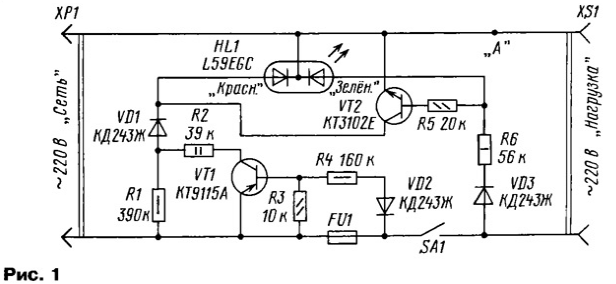
The proposed simple device is assembled from available parts according to the scheme in Fig. 1, is intended for use in an AC circuit with a voltage of 220 V. It allows you to display three different States: 1 - when the cord of the apparatus is inserted in the socket with the supply voltage of 220 V, but the device is off - double-crystal the led shines with a faint red color; 2 - when the machine is turned on (contacts SA1 closed), i.e. the device works, the led glows green; 3 - when in the power supply circuit of the apparatus of the protective fuses fuse FU1 - led HL1 shines bright red.
Plug the load can be of any type, for example, network adapter, battery charger, electric cooker, vacuum cleaner, laboratory power supply. The device may be built into the design, not have their own indications, or for upgrading their old sites the readout is performed by very simple circuits.

Let us examine first the situation when the power cord plugged into a wall socket, but the unit is off (contacts SA1 open). Weak, not tiring sight, but noticeable reddish glow led will remind that on the device is powered by a voltage - when touching live parts you may feel dangerous to the health network 220 V. Alarm system will prevent tampering with, disabling it completely from the network. Many serious industrial appliance manufacturers recommend longer periods in their products, yet to pull the power plug from the outlet and not to rely only on built-in power switch. This is especially true in a lightning storm.
When operating in the above mode, the led is powered through the circuit R1, VD1, power indicator power (much of which is scattered by the the resistor R1) would be about 70 mW.
When contacts SA1 on the machine is supplied with an AC power current 220 V. circuit VD3, R6 receives power green crystal HL1, opens transistor VT2 which bypasses the red crystal HL1 - led shines quite a bright green. Consumed by the node display from the mains power does not exceed 0,6 W (to heat dissipated by R1, the added thermal energy, dissipation current limiting resistor R6). When contacts SA1 the led will Shine green when the load is switched off.
If the alarm blown fuse FU1 offer high voltage p-n-p transistor VT1. HL1 led lights up bright red. If this load will be disconnected, we will be highlighting noticeably weak green crystal HL1. Power dissipation in R2 when the supply voltage is 220 In will not exceed 0.7 W.
When an accident in a supply mains input voltage of about 380 V (actually, if this is required to fuse FU1) dissipated R2 power will not exceed 2 watts, which will lead to a strong heating up, but not able cause it to fire. Given the possible-to-day operation of this site, it was decided to abandon the use of absorbing the excess current film capacitors, which would have to be highly reliable and with a large margin voltage. The use of current-limiting resistors with a large margin power is more reliable, given that in the normal mode, this unit consumes from the mains power 0.6 W max.
In the device assembled in accordance with the scheme in Fig. 1, can be used fixed resistors S1-4, S2-23 S2-33, MLT appropriate power. On the spot R2, R6 is desirable to use a non-combustible domestic resistors R1 -7 (the hull is painted with grey ink) or special imported bursting. These the resistors are preferably set at a height of 15.. .20 mm from the base a printed circuit Board. Rectifier diodes, you can use any silicon, allowing for reverse voltage not less than 600 In, for example, CDD, E, F, CDP D, CDW, G, 1N4006, RL106.
Cheap and common high-voltage transistor VT1 can be replaced CTA, CTB, CTA, MPSA-92, BF493, 2SA1625 M, L, K. the Transistor VT2 is replaced by any of series KT3102, CT, CT, CT, SS9014, 2SC2001, 2SC900. Given the small currents flowing through the crystals HL1, preferably led to take with high luminous efficiency. The author used a double-crystal imported led firm "Kingbright" in a transparent casing with a diameter of 5 mm. brightness - 150 MCD as "red" (GaAsH/GaP) green (GaP) crystals.
Instead, you can use a similar two-anode LEDs, for example, L59SRCG/CC, L59SURK-MGKW, L59EGW, L799SURKMGKW, L119SRGWT/CC, L93WEGC. Mentioned LEDs have good brightness, but the design and style buildings of different LEDs of different series.
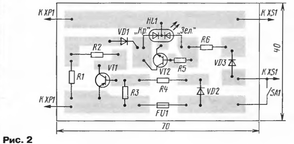
On the circuit Board of this device provides space for the installation of fusible fuse FU1. If you are finalizing the design has "your" similar fuse, the findings of his clips should be connected to the circuit Board two flexible wires of sufficient cross section. If staff switch apparatus, marked on the scheme as SA1, dual (as often happens), the second the group of contacts should be included in the scheme "to the right" spots "And" what not present any difficulties.
The apparatus may be mounted on a printed circuit Board (Fig. 2) of one-sided foil fiberglass dimensions 70x40 mm. the Led can be set as for the PCB, and in any convenient place in the product, for example, instead of the usual single color led, which served as an indicator earlier.

Correctly assembled device does not require networking. When checking it health should take into account that it is electrically connected to the network AC voltage of 220 V, and to take appropriate measures caution. However, the illumination of HL1 will remind that before than something to solder or screw out, you should pull the plug of the cord from outlet. When consumed by the load current of more than 3 And the printed track power should "strengthen" stranded copper wire diameter not less than 1 mm.
Author: A. Butov, S. CORBA Yaroslavl region


