This article describes some improvements locator IPK-01. Multi-level indicator allows you to increase the usability of the device, and the protection device discharge prevents premature exit down the battery. Applied circuit design solutions can be used in other equipment.
The locator IPK-01 is very convenient - has a small footprint, easy to maintain, but, unlike, for example, "outline", has no control of line resistance and not protected from deep discharge battery that under field conditions results in a significant drawback. The proposed device was used to improvements, but they can be used in any other devices where the necessary control parameters (resistance, voltage, etc.) with low degree of precision. Also can find application and warning unit disable the device when a deep discharge battery.
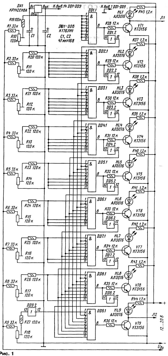
The scheme of multi-level indicator shown in Fig. 1.

(click to enlarge)
The indicator allows to control the parameter of interest in nine control points regardless from the distribution of the parameter. The measuring voltage is input to device Uвх". With a minimum voltage (first threshold) input item DD9.2 there is a low level. The high level output from the DD9.2 goes to pin 1 of the element DD9.1. On the other inputs DD9.1 for this too high level, which results in a high level at the output DD9.1, the opening transistor VT9 and the LEDs HL9.
Upon reaching the first threshold level that is set by the divider R8R17, at all the inputs of the element DD8.1 you receive a high level. The transistor VT8 open, the HL8 led begins to burn. At the same time through the inverter DD8.2 low level goes on the bottom under the scheme the input of the DD9.1, which at its output appears a low level, the transistor VT9 is closed and HL9 led goes out.
Similar processes occur when the voltage of the other levels. So, upon reaching, for example, the eighth level from the inverter DD2.2 to the inputs of all bottom (under the scheme) elements And served a low level, which leads to the closing transistors.
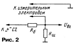
The device monitors the voltage at the input, therefore, to control the other parameter, you must convert it to voltage. In particular, the locator the resistance was controlled by using an input stage, assembled according to the scheme in Fig. 2.

It should be noted that the measured voltage is strongly dependent on supply, therefore, the measuring circuit is powered with stabilized voltage the output of the stabilizer DA1 (see Fig. 1). The resistor RB is necessary to protect source in case of accidental short circuit of the measuring electrodes. Resistor Rш required disabled when the measuring electrodes.
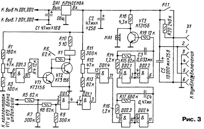
Because extreme values of the resistance - modes in which the locator can't work with the collectors of the output transistors removed from the "L1" and "L2" for supplying to the device alarm and protection, the scheme of which is shown in Fig. 3. It consists of signaling cascades on the elements of the chip and DD2 the transistor VT3, sound emitter HA1, node control elements of the chip DD1 and node enable/disable transistors VT1, VT2 and relay K1.

At power up (turn on a regular toggle switch panel) on pins 1 and 6 connector X1 raises the voltage as the charging of the capacitor C5 is supplied to pins 2 and 5 of the connector. Connector specially soldered symmetrically to avoid any questions on the proper connections, and two contacts better than one in this case. The capacitance of the capacitor C5 is chosen large enough could work node on/off. Relay blocks their contacts K1.1 the resistor R20, the device switches to operation mode.
If in the process, the voltage will drop to dangerous (deep level), the level at the input of the element DD1.3 will be low. High level output DD1.3 open the transistor VT1, VT2 transistor is closed and the relay K1 is released. The device turns off, protecting the battery pack from the dangerous mode deep discharge. The voltage at which protection is triggered, set the adjusted R2 resistor. In the described device, this voltage is chosen to be equal 11B
But before the protection is activated, which disables the device from the power source, a little earlier, at 11.5 V, the alarm device is activated, collected on the elements DD1.4 and DD2.1-DD2.4. The voltage is below 11.5 V perceived element DD1.4 as the lowest level input that leads to the appearance at the output of high level. Start dual tone generator, assembled on the elements DD2.1-DD2.4. The load of the generator is cascade on the VT3 transistor and the emitter HA1.
Appearance on any of the inputs of the element DD1.2 low level, which corresponds to the discovery of transistors VT1 or VT9 multi-level indicator (not both modes allow measurements), leads to the appearance of a low level on the bottom under the scheme the input of the element DD1.4 and triggering alarms.
The emitter HA1 - ZP-1 or any similar suits by volume. Relay K1 - reed REC. It is possible to replace any, but it should be remembered that the current consumed by the relay, is an additional load on the source.
To establish a multi-level indicator on the input you need to file to modify voltage (for example, from the divider) and to simultaneously control its value with a voltmeter. All trimming resistors R10-R18 (see Fig. 1) mounted in the lower (on) position. Served first threshold voltage. Rotation engine resistor R17 achieve ignition HL8 led. After that submit the second threshold voltage. Resistor R16 achieve similar opening the next cascade. Repeat this procedure for the remaining stages. Special the value has a resistor R18. If you need an additional layer between the first threshold and zero, its put a resistor R18.
Protection device adjust similarly. Rotating the trimming resistors engines R2 and R12, achieve actuation of the respective cascades.
Author: G. Sauridi, Ryazan


