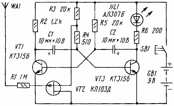
To determine the location of the hidden passage electric the wiring in the walls of the room will help a relatively simple finder, made three transistors (Fig. 2). On two bipolar transistors (VT1, VT3) assembled multivibrator, and on the field (VT2) - electronic key.
The principle of the seeker based on the fact that around electric wire electric field forms - and picks up his seeker.
If you click the switch SB1, but electric field zone of the antenna probe WA1 or no seeker is far away from a network of wires, transistor VT2 is open, the multivibrator does not work, HL1 led is extinguished.
Enough to bring the antenna probe connected chain gate field-effect transistor, to the conductor or just the network wire, the transistor VT2 is closed, shunting the base circuit of the transistor VT3 will end, and the multivibrator will take effect. Will blink the led. Moving the antenna probe close to the wall, it is easy to trace the lodging in her network of wires.
The device allows to find the location of open phase wire. You need to plug in the load, for example a desktop the lamp and move the antenna probe of the device along the transaction. In place where the led stops flashing, you need to search for the fault.
Field-effect transistor may be any of the specified in the scheme of the series, and bipolar - any of the series CT, KT315. All resistors - MLT-0,125, oxide capacitors K50-16 or other small, led - any of a series of AL307, power source - battery "Krona" either battery voltage 6...9, a push-button switch SB - 1 km-1 or similar.

Fig. 2 Schematic diagram of the seeker
The antenna probe is a conical plastic cap, inside which is a metal rod with thread. The rod is attached to the body by nuts on the inside of the casing wear to the rod metal blade, which connect the flexible circuit conductor with the resistor R1 on the Board. The antenna probe may be of different design, for example, in the form of a loop from a piece of thick (5 mm) high voltage the wires used in the TV. The length of the segment 80...100 mm, the ends passed through the holes of the housing and soldered to the corresponding the point of the Board.The desired frequency of oscillation of the multivibrator, and means flash rate of the led can be set by selection of resistors R3, R5 or capacitors C1, C2. For this you need to temporarily disconnect from resistors R3 and R4, the source output of a field-effect transistor and to close the contacts switch.
If you are searching for a fault phase wires sensitivity the device is excessive, it is easy to reduce a decrease in the length antenna probe or disconnecting the conductor connecting the probe with printed Board.
Finder can be used to control the operation of the system automotive ignition. Putting the antenna probe to high voltage finder wires, blinking of the led detect circuit, which is not supplied high voltage, or find the faulty spark plug.
Author: A. Borisov, Novosibirsk, Russia; Publication: www.cxem.net


