


")

Sensitive indicator field may be useful not only for Amateur radio station. Its scope is much wider. This, as well as about good design of field indicator is told in the article.
The task of detection and the detection of weak electromagnetic fields can be successfully solved by using the detector facing the diodes. Volt-ampere characteristic (I-V) converted diode (OD) is shown in Fig. 1. As you can see, its return branch starts from scratch. This form of inverse branches is determined by what OD at zero bias p-n junction is in electrical breakdown, or, in other words, the reverse breakdown voltage of such a diode is zero. This property of the p-n junction is achieved by a high concentration of dopants in the original semiconductor material.
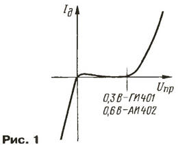
Direct same branch CVC OD corresponding to the characteristic of a conventional diode and various semiconductors begins with a threshold voltage of about 0.3 V for germanium and 0.6 V for gallium arsenide. Thus, the "flipping" diode "upside down", we get a great detector I-V curves starting from zero and with "reverse voltage" is fractions of a volt. In Fig. 2 is shown rotated 180° WAH OD, corresponding to the characteristic is almost perfect for detecting small signals is the best that exists in the modern element base.
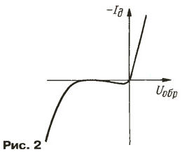
However, a closer look at WAH reversed diode, can be seen vividly pronounced nonlinearity of the third order. This allows the successful application of ML in mixers highly sensitive radio receivers and converters. I'm not sure the purity of the experiment, but in my years of active work on the band 432 MHz (end 70s, collective УSW radio MSU UK3ACF) simple replacement of the diode in the mixer Converter to convert had increased the volume of stations 2…3 points. The ether subjectively seemed "cleaner", since it is almost completely disappeared overload from strong stations.
A schematic diagram. So, build the indicator of electromagnetic field detector on facing the diodes. Scheme of the indicator shown in Fig. 3 corresponds to the the scheme ordinary detector receiver without oscillating circuit.
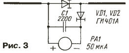
The polarity of the head are correct - the diodes are reversed, the detection occurs on the reverse branches of I-V curves. The sensitivity of the device is determined solely available microammeter needle. When using the device with full the deflection at a current of 50 μa indicator detects cell transmitters networks with distances of several hundred meters. Radio transmitters and УSW FM provide deflection indicator 30…70% of the scale at range 1,5…Almost 2 km, moving with this device in Moscow, rarely cannot find the place where the arrow was deflected. Especially interesting effects can be seen in the apartments on high floors. Sometimes in a completely unpredictable place of the room, the device shows almost full deflection. A detailed study and examination of the surrounding buildings, visible from the window reveals being in line of sight of the transmitting antenna systems.
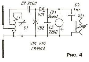
A slight refinement of the device with the introduction of the oscillatory circuit (Fig. 4) more will increase the sensitivity of the device and will allow you to observe spatial pictures of the fields defined radio transmitters or radio stations broadcasting. Now we get a resonance, i.e. a selective indicator of the electromagnetic field. For reliable identification of this or that the radio transmitter is desirable to Supplement the device is high impedance phones (R > 2 com), included AC parallel to the needle device. Settings coil L1 and capacitor C1 are selected based on the desired frequency range. The outlet to the antenna is made from 1/5, and to the detector from 1/3 of the total number of turns coil, starting from the bottom on the output circuit (connected to GND).
The positive qualities of the device can be attributed to the fact that when in fields with high tension detected voltage never within fractions of a volt due to the nature of I-V curves of inverted diode. This quality protects microammeter from failure.
Details. The indicator can be used facing diodes series or GE AI with any alphabetic indices. The capacitor C1 (see Fig. 3), C2 and C3 (Fig. 4) can be type K10-17-1, or any other ceramic Leadless for surface mount, C4 (Fig. 4) km-6 or K10-28, K10-47. AC the capacitor C1 (Fig. 4) type CMP or any other, with an air dielectric.
Coil L1 for operation of the indicator in the range of meter waves must be wound thick (0 > 1 mm), preferably silver plated wire on a ceramic ribbed frame. In the UHF range of the coil L1 can be frameless, made silver plated wire 0 > 2 mm. just 1…3 coils. On higher frequencies it is advisable to use stripline resonators.
As a measuring device used in the instrument microammeter with M current full deflection of 50 μa and the resistance of the frame 1600 Ohms. These the parameters are not critical, so will fit any microammeter, preferably with a current full deflection of not more than 100 μa.
Design. The antenna of the device (Fig. 5) is a broadband dipole with linear polarization.
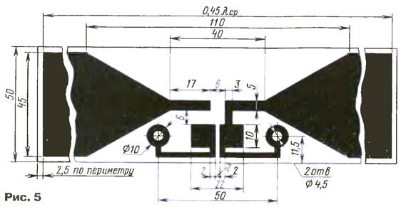
It is made of one-sided foil fiberglass. It are all the elements of the indicator (Fig. 6) and it is attached microammeter using screw their conclusions. This antenna is easily determined polarization observables of the electromagnetic field and even, with a little practice, the change of polarization upon reflection of radio waves from the walls of concrete buildings and large metal objects.

This device can be very useful in radio circles and in educational institutions to illustrate the spatial interference pattern total the electromagnetic field that surrounds us every day.
When using antennas with a more pronounced orientation (multi-element frame, wave TV antenna automatic process) the device can be used for "indoor" games "Fox Hunting" in radio circles. However, in this capacity, he can be useful, for example, to search for hidden radio transmitters.
For operation in the range of short waves (f < 30 MHz) this indicator is not calculated, due to the low efficiency greatly shortened vibrator antenna.
The described device is working properly, I have since 1985, He has never denied and not been repaired. At the time, being a developer of radio transmitters, I always keep this device on your stand, ensuring quality control shielding and lack of radiation not only in the workplace but also in the immediate environment. And I must say that he coped with this task better than official radio monitoring service. I thank him very much!
Author: S. Komarov (UA3ALW), Moscow