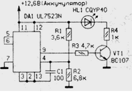
Diagram of discharging the battery with a nominal voltage of 12.6 V and shown in the figure. The threshold of response is chosen to be equal to 11.3 V. Chip DA1 ensures stable operation of the indicator due to included in its composition a reference voltage source (7,15) whose changes in the range temperature 0...75°C does not exceed 15 mV. The output of this source (vyv. 6 DA1) connected to the positive input (pin. 5) of the comparator circuit. On her inverting input (pin. 4) through a divider R1R2 voltage is applied from battery. The resistors of the divider is selected so that when the reduced voltage to the threshold level of the voltage on the pin. 4 chip was equal to a reference voltage. If the voltage on the pin. 4 decreases below the reference, the comparator changes state and the signal appearing at this on the pin. 9 circuits DA1, includes the node display (VT1, R4, HL1).

To adjust the indicator, you can use any stabilized laboratory the power supply unit. It should be connected to the voltage indicator is battery (+12V). The supply voltage should be regulated within 10 to 15, it should be monitored with a digital voltmeter. By reducing voltage to the threshold value HL1 led is lit. If not you will need to change the value of one of the resistors of the divider R1R2, or connect in parallel one additional resistor of 50...500 kω. Connect this resistor in parallel with the resistor R1 will reduce the threshold actuation of the indicator, and R2 in parallel - will increase.
At nominal battery voltage (12V) led is not lit, the indicator consumes less than 2 mA.
In the device, you can use chips KREN or m mA, transistors series KT3102 with any alphabetic indices, LEDs ALBM.
Author: M. Kroszka


