Electrical locators are widely used in various industries. However, despite many years of improvement these devices, even the latest developments [1, 2] have a number of disadvantages:
One of them is a poor receiver selectivity. The capacitor of the antenna circuit of the receiver does not pass the amplifier input signals with frequencies above resonance. Signals of lower frequencies captured by the antenna, including the most active industrial frequency interference, pass freely to the input of the amplifier and amplified them equally with the useful signal. For this reason to improve the ratio signal/interference it is necessary to increase the capacity of the generator, and sometimes even to enter in the receiver pointer instrument [1]. Another significant disadvantage of the known schemes is the complexity of the generator unit and especially of the modulator.
The described scheme the locator redesigned to eliminate these drawbacks. In the proposed form of the device ..allows a precision of 10 cm to determine the centerline of occurrence of telephone cables laid at a depth of 1 m, and also to estimate the depth of the cable and place some damages. The operating range of the device 3-4 km.
The device consists of two parts - the generator and the receiver. To power the generator applies a battery voltage of 24 V. the Receiver is powered by a battery, KBS of 0.5, but can also operate on two or three elements The CFC, and in extreme cases - and from one element of PBS. The battery capacity of the BSC-0,5 provides at least 100 hours of continuous operation of the receiver.
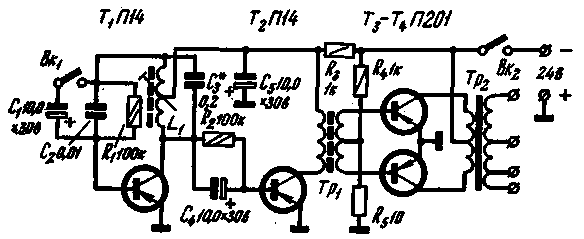
Scheme. Schematic diagram of the generator shown in Fig. 1. The master oscillator to the modulator is assembled on the transistor T1 (A14). When the open switch BK1 transistor T1 circuit L1C3 in the collector circuit of elements and R1C2 in the base circuit forms a type of three-point LC oscillator with an operating frequency of 1000 Hz. Partial incorporation of a circuit in the collector circuit allows you to connect a significant load directly to the collector of transistor T1 without a noticeable decrease in the quality factor of the circuit as a whole. The time constant of the base circuit is chosen close to the oscillation period. When you connect with BK1 capacitor C1 time constant of the base circuit increases dramatically and the generator becomes widely known for use in УSW the range of the superregenerator, only in this case the modulation frequency is required 2-3 Hz.

Fig.1
Cascade transistor T2 (A14) is the buffer between the generator and a powerful push-pull output stage, assembled on the transistors T3, T4 (P). The resistance R2 creates the necessary initial mode the transistor T2 current; resistance R3 serves to reduce the supply voltage applied to the first two low-power transistors in order to protect from over-permissible parameters (especially when dealing with modulation). Resistance R4, R5, create the necessary initial mode transistors of the output stage to maximize their use for undistorted output power. Partitioned winding of the output transformer allows you to align the output of the generator to the load in the 1 - 2 Ohm, 50 Ohm and 200 Ohm. The power output of the generator is 5-8 watts. If you need to increase the generator power output transistors can be replaced by L4, and between the transistor T2 and the output stage to add one cascade assembled on the common-emitter transistor P.
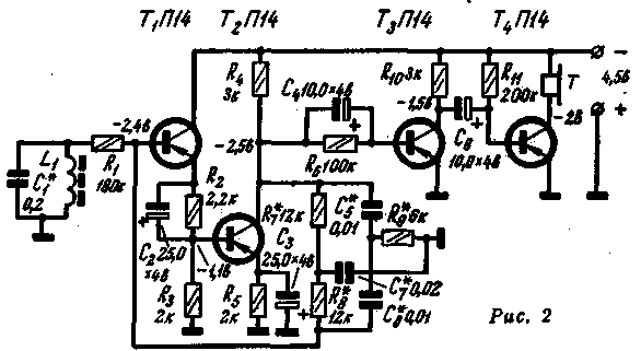
Schematic diagram of the receiver with a magnetic antenna is presented in Fig. 2.

Fig.2
The antenna circuit L1C1 tuned to the frequency of the generator. The audio frequency voltage is supplied through a resistance R1 to the input of the amplifier, harvested from the four low-power transistors (A14 or other). The first two transistors form a along with a double T-shaped bridge in the circuit of the negative feedback selective amplifier. The use of conductivity bridge allows you to get rid of transient vessels and to obtain temperature stable circuit [3]. The resistance R1 necessary to ensure normal working conditions selective amplifier with such a bridge. Two cascade transistors T3 and T4 provide the necessary amplification. Initial mode of these transistors is determined by the resistances R6 and R11. Phones - high resistance, type TONE-2.
Design and details
The generator is mounted on a laminated bakelite circuit Board attached at the corners to the front panel and insert into the casing on slide rails. Board size 150X100 mm, thickness 2 mm. Application fees of insulating material allows you to position the mounting petals in the most convenient locations and thereby drastically reduce the number of connecting wires or to use a printed wiring. The front panel hosts the tumblers UK and BK2, output terminals and the connecting terminals of the power supply. Other parts mounted on the Board. Power transistors are slightly raised above the Board with the help of the bushings and have a small horseshoe-shaped radiators from aluminum.
Coil L1 contains 500+500 turns of wire PEL 0.1 and executed on core SB-3. The Tp1 transformer wound on a ferrite ring an outer diameter of 8 mm and a section of 2x3 mm; the primary winding has 300 turns of wire PEL of 0.1, and the secondary-80+80 turns of wire PEL of 0.15. Transformer Tp2 assembled on the core of transformer steel plates sh-19, the thickness of 25 mm. the Primary winding it contains 130+130 turns of wire PEL is 0.51, and the secondary - 40+160+200 turns of wire, respectively PEL 1,2, PEL 0,51, PEL 0,33.
The receiver is mounted with the antenna circuit capacitor C1 is executed on the Board of Micarta thickness of 1-2 mm, fastened with studs inside of a vinyl plastic tube outside diameter 24mm, which serves as both a holder body with a magnetic antenna. This housing can be rotated relative to the holder at an angle of 120° and fixed in any position that is needed for different search modes. Antenna coil wound on a standard ferrite rod f-600 dimensions h mm and contains 9 sections 200 turns each, made by cable PELSHO 0.15; winding type "universal". In the upper part of the holder has a box for the battery KTS and phone jacks.
The transistors T3 and T4 are preferably selected with a=40-70.
The establishment of the device
The method of adjustment of the device does not differ in principle from that described by V. Romanovichi and I. Strizhevskaya [2].. you only Need to consider the following. The oscillator frequency is controlled by the core of the coil L1 and the selection of the capacitor C3. The resistance of R2 should be chosen to be off before the transistor T1, the collector current of transistor T2 was 8-10 mA, it is Desirable that the transistors T3 and T4 were similar. The current drawn from the battery depends on the load and can reach up to 1 A.
When establishing the receiver, special attention should be paid to careful selection of the elements of the bridge depends on the gain on the "carrier" frequency. It is best to follow the methodology proposed by E. Coupleskim [3]. Mode the first two stages is set automatically from the feedback DC mode, your amps should be selected through resistors R6 and R11 so that the voltage at the collector of transistor T3 was about a quarter of the supply voltage and the collector of the transistor T4 is about half of this voltage. At a voltage of 4.5 V receiver consumes 4-5 mA.
Literature:
1. Zotov A. A. the Locator of underground pipelines, "Gas industry", 1962, No. 9.
2. Romanovich V., Strizhevskaya I. Locator, "Radio", 1961, No. 1.
3. Kuvlesky E. I. Electoral RC-amplifier on a semiconductor triode direct coupled, "radio", 1961, No. 9.
Author: Troyanovsky; Publication: N. Bolshakov, rf.atnn.ru


