


")

An ordinary compass is sensitive to magnetic field. Enough to bring before him the magnetized end of a screwdriver, as the needle will deflect. But, unfortunately, after that, the arrow will still wobble. So enjoy this indicator is not always convenient. The need for this measurement device often occurs.
Assembled from multiple parts, the indicator is completely and relatively non-sensitive. They, for example, you can define the magnetization of the razor blade or screwdriver clockwise.
The principle of operation of the indicator is extremely simple: if near the coil to carry a magnetized object, then its findings will be some EMF, which and just need to reinforce and apply for the indicator, such as lamp pocket lantern.
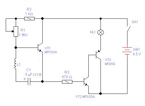
Fig.1. Schematic diagram of the magnetization
In figure 1 is represented a schematic diagram of the indicator. Sensor is the coil L1 wound on a steel core. It is connected via the capacitor C1 to the amplifying cascade, performed on the transistor VT1. Mode the cascade operation mode is set by resistors R1 and R2. Depending on the parameters of the transistor the optimal operation mode is set by the variable resistor R1.
In the emitter circuit of the transistor of the first stage included composite транзисторVT2VT3 of transistors of different structure. The burden of the transistor is the warning light HL1. To limit the maximum collector current VT3 transistor in the base circuit of the transistor VT2 is a resistor R3.
As the sensor is best to use a coil with a core from the electromagnetic relay PCM RES RES9 or other, the resistance of the winding not less than 200 Ohms. The greater the resistance of the winding, the more sensitive the indicator.
Details
Instead of the transistor MPA you can apply KT315 with any letter index. The main thing is that the reverse current of the collector was not too big. Instead MP25B you can use any transistors series MP, MP with a transmission coefficient of not less than 40. Capacitors, fixed resistors - MLT-0,25, variable resistor - SP-1. Warning light - on voltage of 3.5 In and perhaps less current, for example, 0.15 A.
Establishing
After mounting the parts on the PCB or mounted installation and check the correctness of connections to supply power. After you need to install the engine variable resistor so that the filament the lamp barely glowed. If the filament glows too bright even at the top under the scheme the position of the slider, so the resistance of the resistor R2 is too small and its value needs to be increased. Then in front of the sensor core is placed briefly the permanent magnet. Lamp is bright flare. If the flash is weak, it indicates that the transfer ratio of the transistor VT1 is too small. It will have to be replaced.
During operation of the indicator variable resistor install first, as you lower the brightness of the lamp, and then hold the core sensor test subject. When checking weakly magnetized objects the initial brightness of the lamp should slightly increase, to better noticeable changes.
Literature
Author: Alexander Shepetko, Lugansk, Ukraine; Publication: N. Bolshakov, rf.atnn.ru