Parasitic currents on the braid of the coaxial cable going from radio station to the antenna arise under asymmetric power last, in case of any fault such as breakage of the counterweight or the braid at the point of connection with antenna contact antenna or counterweight with other items and in many other cases. Among the consequences that result from parasitic currents on the braid cable, it is necessary to mention the emergence of the RF voltage on the transceiver, interference on TV neighbors, reducing the efficiency of the antenna-feeder tract. Usually used SWR meter can not always determine asymmetric the mode of operation of the cable, and does not provide operational control situation.
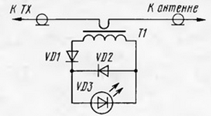
Attention ham radio offers a simple and very convenient indicator of the current the braided cable. Its scheme is shown in the figure.

The heart of the device is current the transformer T1 is made on the annular magnetic core of ferrite magnetic permeability 50...1000. Ring sizes are selected such that it (with wound secondary winding) sat tight on the cable, I miss using it hole. The cable is single-turn primary winding. Since indicated current on the outer surface of the braid, the integrity of the cable is not broken, even the insulation should not be removed.
The secondary winding of the transformer T1 consists of 15 turns of wire sew or PELSHO diameter 0.3...0.5 mm. RF voltage from the secondary winding is rectified by diode VD1 is supplied to light the diode VD3. VD2 diode protects the led from accidental pulse reverse voltage. Diodes VD1 and VD2 can be any high frequency, for example, CDA, the led fit any type.
In establishing the device does not need. To scan it to a controllable cable connect an agreed equivalent load and include transmitter output power 15-20W - the led never lights up. If we connect any antenna only to the center conductor of the cable - led will light up.
This appliance responds well and the "antenna barbarians", of course, the included transmitter.
The sensitivity of the device can be improved by creating a symmetrical secondary winding of the transformer T1 (2x15 turns) and connecting the right circuit output LEDs with an average point - get a push-pull rectifier. The same the effect will be and the bridge rectifier with four diodes.
Author: A. Prokudin (RN9APE)


