


")

Single-stage amplifier 3H (Fig.1)
This is the simplest design that allows you to demonstrate amplification the ability of the transistor. However, the gain of the voltage is small - it does not exceed 6, so the scope of application of such devices is limited. The less it can be connected to, say, touch the radio (it needs to be loaded to a resistor of 10 ohms) and using the headset BF1 broadcasts a local radio station.
The amplified signal is supplied to input terminals X1, x2, and the supply voltage (as in all the other designs by this author, it is 6 In four galvanic cell voltage of 1.5 V connected in series) served on a nest XS, X4. The divider R1R2 sets the bias voltage on the basis transistor, and a resistor R3 provides a feedback current, which contributes to temperature stabilization of the amplifier.
How is the stabilization? Suppose that under the influence of temperature increased collector current of the transistor. Will increase accordingly fall the voltage across the resistor R3. In the end, will decrease the emitter current, and hence current collector - he will reach the original value.
Load amplifier - headset impedance 60… 100 Ohms.
Check the operation of the amplifier is easy, you need to touch the input Jack X1, for example, the forceps - the phone should be heard a faint buzzing, as the result crosstalk of the alternating current. The collector current of the transistor is about 3 mA.
Two-stage amplifier 3H transistors of different structures (Fig.2)
It is made with a direct bond between the cascades and deep negative feedback DC, making it a mode independent of ambient temperature. The basis for the thermal stability of the resistor R4, "working" is similar to the resistor R3 in the previous design.
The amplifier is more sensitive compared to single-stage - coefficient gain voltage reaches 20. For input jacks, you can submit AC the voltage amplitude of 30 mV, otherwise there will be distortion, listening in the head phone.
Check the amp by touching the tweezers (or finger) input jacks X1 - the phone will emit a loud sound. The amplifier consumes a current of about 8 mA.
This design can be used to amplify weak signals, for example, from microphone. And of course, it will significantly boost the signal 3H, remove from the load detector of the receiver.
Two-stage amplifier 3H transistors of the same structure (Fig. 3)
It also used a direct link between the cascades, but stabilization the mode of operation is somewhat different from previous designs. Assume that the current the collector of the transistor VT1 is decreased. The voltage drop across the transistor will increase, which will lead to an increase in the voltage across the resistor R3. included in the emitter circuit of the transistor VT2. Due to the connection of transistors through a resistor R2, will increase the base current of the input transistor, which will lead to an increase in its current collector. 8 the result of the initial change in the collector current of this transistor is compensated.
The sensitivity of the amplifier is very high, the gain reaches 100. The gain strongly depends on the capacitance of the capacitor C2 if disabled, the gain will decrease. The input voltage should be no more than 2 mV.
The amplifier works well with a crystal detector, with electret microphone and other sources of weak signals. The current consumed by the amplifier is about 2 mA.
Push-pull power amplifier 3H (Fig. 4)
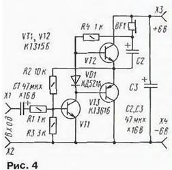
He performed on the transistors of different structure and has a voltage gain about 10. The highest input voltage may be 0.1 V.
The two-stage amplifier: the first assembled on the transistor VT1, the second - on VT2 and VT3 different patterns. The first stage amplifies the signal 3H voltage, both half equally. The second amplifies the signal current, but the cascade transistor VT2 is "working" with the positive half waves, and the transistor VT3 - negative.
Mode DC voltage is selected such that the voltage at the connection point emitters of the transistors of the second cascade is approximately half the voltage power source. This is achieved by the inclusion of a feedback resistor R2. Current the collector of the input transistor flowing through the diode VD1, leads to a drop in it voltage, which is the bias voltage at the bases of the output transistors (relative to their emitters, it can reduce distortion the amplified signal.
Load (several parallel connected headphones or dynamic head) is connected to the amplifier via the oxide capacitor C2. If the amplifier will work on a dynamic head (resistance 8…10 Ohm), the capacity of this the capacitor should be at least twice the amount.
Note the load connection of the first cascade of the resistor R4. It upper circuit output not connected with the positive power supply, as is usually done, and with the lower output load.
This so-called voltage boost circuit. in the base circuit of output transistors receives a small voltage 3H positive feedback leveling the working conditions of the transistors.
Split level indicator voltage (Fig. 5)
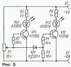
Such a device can be used, for example, to display the "exhaustion" of the battery power or indication of the level of the reproduced signal in a domestic tape recorder. The layout of the indicator will demonstrate how it works.
In the lower circuit on the position of the slider of the variable resistor R1 both transistors closed, LEDs HL1, HL2 repaid. When you move the cursor up resistor, the voltage across it increases. When it reaches the voltage of opening transistor VT1, the led will flash HL1.
If you continue to move the engine, there will come a time when after the diode VD1 opens the transistor VT2. Will flash and the led HL2. In other words, small the voltage at the input of the indicator causes the illumination-only led HL1, and more - both lights are on.
Gradually reducing the input voltage to a variable resistor, note that the first turns off the led HL2, and then HL1. The brightness of the led depends on limiting resistors R3 and R6: by increasing their resistances brightness falls.
To attach the indicator to a real device, you need to disconnect the upper circuit output of the variable resistor from positive wire of the power source and apply controlled tension to the extreme conclusions of this resistor. Moving his engine choose a threshold "trigger" indicator.
When monitoring only the voltage of the power source is permissible to set in place HL2 led green glow (ALG).
Three-level voltage indicator (Fig. 6)
It produces light signals according to the principle of less than normal - the norm above the norm. For this indicator used two led's red glow and one green.
At a certain strain on the engine, the variable resistor R1 (the voltage in normal") both transistors are closed and "works" only the green led HL3. Moving the engine up resistor to the circuit increases the voltage ("above the norm"). Opens the transistor VT1. The HL3 led goes out and No lit. If the engine is to move down and thus reduce the voltage on it ("less than normal"), the transistor VT1 is closed, a VT2 will open. Will observed this pattern: first, the led goes out HL1, then turn on and soon goes out.
HL3 and finally breaks out of HL2.
Because of the low sensitivity of the indicator is obtained a smooth transition from extinction one led to the ignition of the other: not out yet completely, for example, HL1, and already ignited HL3.
The Schmitt trigger (Fig. 7)
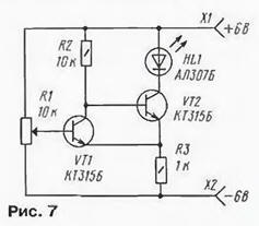
As you know, this device is generally used to convert a slowly changing the voltage in a square wave signal.
When the slider of the variable resistor R1 is lower according to the scheme position transistor VT1 is closed. The voltage at its collector high. As a result transistor VT2 is open, which means that HL1 led is lit. On the resistor R3 forms a voltage drop.
Slowly dragging the slider of the variable resistor up under the scheme will be achieved the moment when there is an abrupt opening of the transistor VT1 and closing VT2. This happens when you exceed the voltage on the base of VT1 voltage drop the resistor R3. The led will turn off.
If you then move the engine down, the trigger will return to the original position - the led will flash. This happens when the voltage on the smaller engine, than the switching voltage of the led.
Waiting multivibrator (Fig. 8)
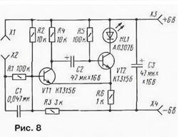
Such a device has one stable state and enters another only when the input signal. In this case, the multivibrator generates a pulse "its duration regardless of the length of the input. Verify this conducted the experiment with the layout of the proposed device.
In the initial state, the transistor VT2 is open, HL1 led is lit. Enough now briefly to close the nest Hi x2, so that the current pulse through capacitor C1 was opened by the transistor VT1, the Voltage at its collector decreases, and the capacitor C2 will be connected to the base of transistor VT2 and the polarity such he closes. The led will turn off.
The capacitor will be discharged. the discharge current will flow through resistor R5, hold the transistor VT2 is in the closed state. Once the capacitor discharged, the transistor VT2 will reopen and the multivibrator will go in again the "standby"mode.
Duration generated by the multivibrator pulse (duration being in an unstable state) is not affected or the duration runs, and is determined by the resistance of the resistor R5 and the capacitance of the capacitor C2. If be connected parallel to the capacitor C2 of the same capacity, the led twice as long will remain in a suppressed state.
Symmetrical multivibrator (Fig. 9)
This design generates at its outputs the pulses and pauses of the same duration. This is achieved by inclusion in the shoulders of the multivibrator parts the same denominations. This form of signal is often called the "meander".
Actually this multivibrator is a two-stage amplifier whose output one of the cascade connected to the input of another. Therefore, after power always happens that after some time one transistor of the multivibrator is open and the other closed.
Assume that you have opened the transistor VT1, and thus, led lights HL1. The capacitor C1 is charged by a voltage close to the supply voltage in accordance with the specified polarity on it, and is discharged through the resistors R1 and R2. As his discharge decreases closing the voltage at the base of the transistor VT2 and soon it opens, led should be illuminated HL2. Now begins to run out the capacitor C2 while holding the transistor VT1 is closed. The process then repeats.
The duration of illumination of the LEDs depends on the values of capacitors C1 and C2 and resistors R2 and R3. Enough, for example, be connected in parallel to the resistors R2 and R3 by the same resistor as the frequency of outbreaks of LEDs will increase. If connect a resistor in parallel to only one of base, one can observe unequal length a - flashing LEDs-multivibrator becomes unbalanced.
The generator of sound frequency (Fig. 10)
It has the symmetrical multivibrator, but the frequency of it pulses greatly enhanced - capacitance relation is reduced to 1000 time. In addition, the base resistors R3 and R4 connected to the variable R1. and the signal with loads of the right shoulder of the multivibrator filed an amplifier, assembled on the VT3 transistor. The load of the amplifier serves as a head phone BF1.
Listening to the phone, move the slider of the variable resistor from the bottom position at the top. In this case the phone will be able to listen to the changing the tone of the sound.
Metronome (Fig. 11)
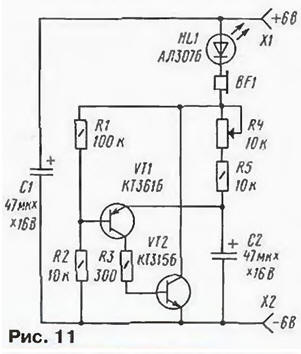
The proposed metronome, in fact, is the generator of short pulses. Following with a certain frequency, these pulses are tapped in the head phone BF1 in the form of clicks. They help a beginner musician to withstand preset rhythm when playing on a particular instrument.
If you listen to the sound of a metronome uncomfortable, with the pulse repetition rate you can observe the led flashes НL1.
How does the metronome? When the power begins to charge the capacitor C2 - the led head phone and resistors R4, R5. At a certain the voltage on the capacitor open both transistors. And almost immediately the capacitor discharges through the circuit the collector - emitter of the transistor VT1, resistor R3 and the base-emitter of the transistor VT2. In the phone you hear a click, at the same time led flashes.
The frequency of the clicks and flashes of the led is adjusted depending on the desired rhythm a variable resistor R4. If you increase the resistance of the resistor (engine moving up the diagram) the charging time of the capacitor increases the repetition rate of clicks decreases, and Vice versa.
The generator of short pulses (Fig. 12)
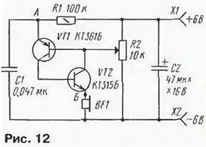
It produces pulses of small duration, the repetition rate of is sound region. This generator can be used, for example, in the alarm device.
When the generator serves the supply voltage, the transistors are closed and the capacitor C1 begins to charge through resistor R1. The voltage at it will increase not linearly, but exponentially - this curve can be observed on the oscilloscope screen connected to point a and the minus of the power supply (socket x2).
As the voltage on the capacitor C1 reaches a predetermined value, transistors VT1, VT2 (they assembled the so-called analog SCR - semiconductor switching device) abruptly open. The capacitor C1 is quickly discharged to the phone BF1. Short voltage pulse almost rectangular shape can be observed on the oscilloscope whose input is in this case should be connected to point B.
After the discharge of the capacitor, the transistors are closed and the process repeats. The value of the voltage at which "trigger" the analogue of the SCR, set the variable resistor R2.
Simulator sound jumping ball (Fig. 13)
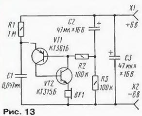
Using the analogue of the SCR, which was used in the previous design, can to assemble the device, simulating the sound signal, which is characteristic for jumping a metal ball on a hard surface.
The duration of the current pulse flowing through the phone BF1, constant and depends mainly on the capacitance of the capacitor C1, and the voltage value on this the condenser, which will open the equivalent of SCR. depends on the voltage drop across the resistor RЗ. These are the main provisions necessary to understand the principle of operation of the device.
So, with the device applied voltage. Immediately starts charging the capacitor C1, and the voltage across it increases gradually. The capacitor C2 is discharged, therefore, the voltage across the resistor R3 reaches the supply voltage. Analogue the SCR opens with a substantial voltage across the capacitor C1. Clicks in phone BF1 have the maximum volume.
As the charging of the capacitor C2 the voltage drop on the resistor R3 decreases. Analog SCR opens at lower voltage on the capacitor C1. Click volume decreases and the frequency increases. The impression smooth reducing the height of the jump ball. Soon, when the capacitor C2 fully charged, the sound will disappear. To run the simulator shut off power, short-short sockets X1 and x2, to discharge the capacitors C1, C2, and then re-apply mains voltage to the simulator.
The security device (Fig. 14)
There are many e-guard devices around the protected object stretch thin electric wire, the ends of which are connected to signalling device, the offender Is to cut the wire, as the detector will trigger and will let you know of the uninvited guest.
Such a device can be assembled in the form of layout and clearly acquainted with it action. While connected to terminals X1 and x2 of security a wire, analog of SCR on transistors VT1, VT2 is closed, HL1 led is extinguished. Once happens broken wire, similar to the SCR is triggered, the led will be lit. No attempts to restore the integrity of the wire will shut down the alarm - analog the SCR will remain in the open state.
To bring the device to its original position, it is enough for the moment turn off the power.
The indicator of hidden wiring (Fig. 15)
It is often necessary (for example, during the repair of the apartment) to know where padded wire wiring hidden so you don't accidentally damage them. For that there are many different indicators. One of them can be done sound and collect three transistors. And two of them - VT1 and VT2 will be connected in a so-called composite transistor. They collect the first amplifier stage is 3H,and VT3 is the second cascade.
Overall gain can be changed by the variable resistor R5. Load is low-impedance headset BF1. The maximum volume is limited resistor R8.
To the amplifier connect the sensor antenna WA1. Her role will perform ordinary copper wire with a diameter of 0,8…1 mm and a length of about half a meter. On the other end it is desirable to strengthen (even better to solder) a small metal plate. From her the size depends on the sensitivity of the indicator.
To test the functionality of the indicator enough to touch the finger of the antenna - and in the phone you will hear the hum, the volume of which depends on the level of interference and the position of the engine variable resistor.
The same sound appears during the movement of the plate along the intended hidden the electrical wiring. At maximum volume, determine the exact location the pipeline transaction.
Probe for "continuity test" installation (Fig. 16)
This device checks the integrity of the connections between the parts or another electronic device call" the cables, check the various radio components, if the resistance does not exceed 2 ohms.
The probe used Schmitt trigger, transistors VT1 and VT2. As the reader will recall (see Fig. 7), such flip-flop has two stable States, which alter the input signal. When the input styli (or plug) X1 and x2 are open, the trigger is in one of the States. HL1 led is extinguished. It should be close between a stylus or touch them serviceable check the low-impedance circuit (say, a connecting conduit between the findings of the details) as a trigger switch to another stable state will be a spark led HL1. Moreover, the brightness of the led depends on the resistance of a circuit in from 0 to 2 ohms.
In the case of test circuits of high impedance trigger will remain in their original the state and the led will "keep silence".
Alarm overcurrent (Fig. 17)
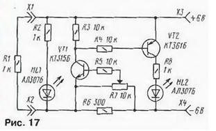
Sometimes, you need to monitor the current consumed by the load, and in case exceeded - time to turn off the power source that is not out of order load or source. To perform such task are the transmitters, announcing the excess current consumption. A special role belongs to such device during a short circuit in the load circuit.
What is the principle of operation of the indicator? To understand it will allow the proposed layout the device is made of two transistors. If the resistor R1 is disconnected from the sockets X1, x2, load to a power source (connected to terminals X3, X4) will be circuit of a resistor R2 and led HL1 - it burns, informing about the presence the voltage at the sockets X1 and x2. When this current flows through the sensor motion detector the resistor R6. But the voltage drop is small, therefore the transistor VT1 closed. Respectively closed and transistor VT2, the led HL2 repaid. Worth be connected to terminals X1, x2 additional load in the form of a resistor R1 and thus increase the total current as a voltage drop across the resistor R6 will increase. At a corresponding position of the slider of the variable resistor R7, which set the threshold of the detector, the transistors VT1 and VT2 open. Will flash the led HL2 and will signal a critical situation. HL1 led remains lit, indicating the presence of voltage at the load.
And what will happen if a short circuit in the load? It is enough close (briefly) socket X1 and x2. Again the led will flash HL2, a HL1 will go out.
The slider of the variable resistor can be set to a position at which the detector will not respond to a connection of the resistor R1 resistance 1 com, but "work", when in place more of the load is a resistor, say, a resistance of 300 Ohms (it is included in the kit).
The prefix "Color sound" (Fig. 18)
One of the most popular Amateur radio structures - installation of lighting (Sdes). It is also called "illuminated musical box". When you connect like this consoles to the sound source, on the screen appear the most bizarre color the outbreaks.
Another kit design - a simple device that allows you to explore with the principle of obtaining the "color of sound". At the entrance, consoles are two frequency filter - C1R4 and R3C2. The first of them passes the higher frequencies,
and the second - lowest. Selected filters the signals go to an amplifier cascades, loads of which are LEDs. Moreover, in the channel of the higher frequencies is HL1 led green glow, and in the channel in the lower frequencies - red (HL2).
The source audio signal may be, for example, radio or recorder. To the dynamic head of one of them you need to connect two wires in isolation and connect them to the input sockets X1 and x2 consoles. Listening a different tune, you will observe the flash LEDs. In addition, it is easy to distinguish between "response" LEDs Eeyore sounds of varying pitch. Say, at the sound of the drum will flash a red led glow, and the sound of the violin will cause the led flash green. The brightness of the LEDs set the volume control of the audio source.
The temperature indicator (Fig. 19)
All known conventional mercury thermometer, the mercury which rises when the increased body temperature. In this case, the sensor is a mercury expanding with heat.
There are many electronic components that are also sensitive to temperature. They sometimes become sensors in the devices intended to measure temperature of, say, the environment, or indication of exceeding its specified norm.
As such a heat-sensitive element in the proposed layout used silicon diode VD1. It is included in the emitter circuit of the transistor VT1. The initial current through the diode set (variable resistor R1) such that HL1 led is barely lit.
If you now touch the diode with a finger or any hot object, it the resistance will decrease, and thus will decrease and the voltage drop on it. In the result will increase the collector current of the transistor VT1 and the voltage drop across the resistor R3. Transistor VT2 will begin to close, and VT3, on the contrary, to open up. The brightness of the led will increase. After cooling diode brightness of the led reaches the initial value.
Similar results can be obtained if heating of the transistor VT1. But the heating transistor VT2, and the more VT3 on the brightness of the led is almost not impact - too little change of current through them.
These experiments show that the parameters of semiconductor devices (diodes and transistors) depend on the ambient temperature.
Metal detector (Fig. 20)
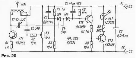
He responds to the ia approximation to the magnetic antenna WA1. And the antenna itself is part of the high-frequency generator, which is made on transistor VT1. The oscillator frequency can be changed by a variable capacitor (used capacitor CPC-2 capacitance change from 25 to 150 pF).
From the output of the generator high-frequency signal flows through the capacitor C4 to the rectifier (or detector), assembled on the diodes VD1, VD2. The voltage eye-catching on the chain C5R6, opens the transistors VT2, VT3. Led HL1 lit. This state achieve a variable displacement engine resistor R3 from the bottom on the output circuit.
Approaching a magnetic antenna such as scissors, will cause such a change the frequency of the generator, the voltage on the base of the transistor VT2 will start to decrease. The led will extinguish.
Changing the frequency of the oscillator capacitor C1 and selecting the position of the slider variable resistor R3, will be able to achieve the highest sensitivity of the detector - it will respond to a metallic object from a distance of several inches to a magnetic antenna. It may be possible to adjust the detector so that he will be able to respond even to the approach of the hand (in this embodiment, the frequency the generator will vary due to changes in the capacitance of the oscillatory circuit generator).
Magnetic antenna is made on the rod with diameter of 8 mm and a length of 80 mm ferrite NN. The winding is wound in a single layer of wire sew-2 of 0.25. It contains 83 loop with a branch from 9-turns, starting from output 1.
Author: I. Bakouchev