


")

Many people today are searching for treasure, lost coins and jewelry products. For this work, undoubtedly you need a good device - a metal detector. The author of the present article has collected such a device, tested it in action and recommends to repeat it to everyone.
The basis of the metal detector was a device described in the book the beast Lord E. "Electronic devices for home" (Energoatomizdat, 1984). During prototyping and validation of the device was upgraded alternator, replaced element base on more accessible, simplified output stage of indicator of the presence metal entered the dial gauge, installed a noise filter.
The principle of operation of the resulting detector "transmission - reception" is reception of signals reflected from a metal object. This signal occurs due to the impact of the metal magnetic alternating field of the transmitting (radiating) coil of the metal detector, connected to a generator.
Take-up spool is located in one plane with the transmission in such a way that through the magnetic lines of force generate a small EMF. On the findings the coil signal is absent or very small. A further decrease of the signal ensures the compensation node.
If the field coils hits a metal object, an inductive connection between them changes on the conclusions of the receive coil appears an electrical signal which amplified, rectified, and then filtered. In the end, at the output of the filter you receive a constant voltage, which increases when approaching the coils to metal object.
This signal is fed to one input of a comparison site, which compares with the reference voltage, which is applied to its second input. Level the reference voltage is adjusted in such a way that even a slight increase signal leads to a significant change of the signal level at the output node comparison. This, in turn, actuates the electronic key, managing the sound signaling the detection of a metal object.
Diagram of the improved detector is shown in Fig. 1. Generator, performed on the VT2 transistor and circuit L1C3, operates at a frequency of about 4.6 kHz. Low frequency generator provides, on the one hand, weak reaction metal detector to unwanted signals (for example, resulting from the wet sand, small pieces of metal, etc.), and with another - good sensitivity. If desired, the oscillator frequency can be rebuilt in a change parameters parts L1, C3 and L2, C6 and filter R16C11.
(click to enlarge)
Depth of detection of objects depends on the frequency of the working signal, its power, the size of the inductors, as well as the size and shape of the object and its position. The higher the frequency, the shallower the depth of detection of small items. The larger the inductance, the greater the depth discovery. For example, the metal detector detects coin diameter 25 mm at a distance of 13 cm, and an aluminum plate with dimensions 100x100 mm to a distance of 40 cm.
The transistor oscillator is assembled on the Assembly. Transistor VT2 works directly in the generator, aVT1 together with the divider of the details of R2-R4 - in the heat stabilizer that provides temperature compensation.
The signals to the receiving coil L2, are limited in amplitude (when the presence of a large metal object) diodes VD1, VD2, and then amplified OH DA1.1. The input to this IC is fed via the capacitor C5, resistors R7- R10 and capacitor C8, the compensation signal generator - it reduces incoming the coil L2, the signal from the coil L1 in the absence of near metal objects.
After amplification, the signal passes through the low pass filter R16C11 and straightens OU DA1.2. When a positive input voltage received at the non-inverted input IC, diode VD3 is open and provides negative feedback. Charging the capacitor C12, the arrow indicator PA1 rejected. When negative input voltage, the diode is closed, no feedback, at the cathode diode - zero voltage.
The signal from the detector is smoothed by the filter R21C14R22C15 and is supplied to the comparator DA2.1, where it is compared with a reference voltage, an adjustable variables resistors R23 (roughly) and R25 (exactly). Upon actuation of the voltage comparator at the output is reduced, the transistor VT3 is closed, starts to work tone generator, assembled on OU DA2.2. Its output signal is fed to the power amplifier is performed on the transistor VT4, the load of which is the headset BF1 (hearing aid). The volume of sound in a small within regulate a variable resistor R38.
The output stage is powered from a separate source, which eliminates the possibility the excitation device. The main part of the detector is powered from the source 12 V (battery), using the stabilizer DA3 reduced to 9 V.
Details of the detector are mounted on three printed circuit boards (Fig. 2-4) from sided foil fiberglass. They are designed for use resistors MLT-0,125, R10 JS4-1, capacitors C3, C6 - K71-7.
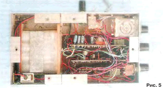
Transistor Assembly TSA permissible to replace CTS, but have change the drawing of the PCB. Dial indicator PA1 - level indicator the recording of any tape recorder. Fees and other details of the detector placed in the body of insulating material (Fig. 5).
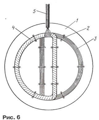
Special attention should be paid to the manufacture of coils. Their is wound on the mandrel with a diameter of 140 mm, which is good to use a glass jar. Each coil consists of 200 turns of enameled copper wire diameter 0.27 mm with a branch from the middle of the coil. Before removing the coil from the mandrel, it tie in three or four different places, and after removing wrapped with a durable thread that coils tightly to each other. Further, the coil shape, it is shown in Fig. 6, and attach them to the plastic plate 1 thread 2. Transmitting coil 3 features a downstairs reception room 4 at the top. Take-up spool must be equipped with an aluminum shield with a gap that prevents the formation the closed loop. The findings of the coils connect to the rest of the instrument cable 5 in shielded braid. The distance between the vertical (in the figure) turns coils must be equal to 25 mm, it finally specified after the configuration the metal detector on the minimum indicator PA1 in the absence of near coils of a metal object.
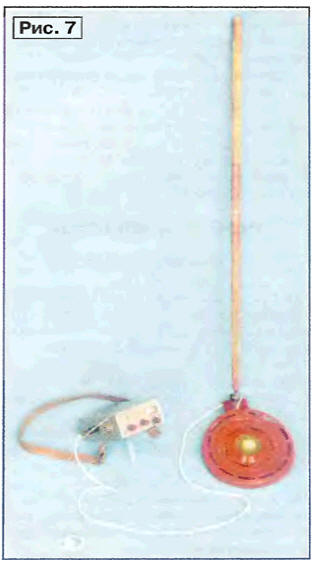
After the final mounting of the coils they cover up the top decorative housing and fixed thereto by a rod (Fig. 7).
Setup of the detector is to install the engine resistor R10 when the middle position of the R8 engine in a position so that the indicator arrow PA1 was on the "zero" mark (for convenience, the arrow is set on average mark of the scale selection resistor R19. Possibly, for this purpose you will have to change connecting the findings of one of the coils of the generator.
During operation of the metal detector, after his 20-minute setting the operating mode, resistor R8 achieve "zero" the dial indicator. After that, variable resistors R25 and R23 set the reference voltage, close to triggering of the comparator and the emergence of tonal sound. Naturally, this setting is carried out in the absence of close coils of metal.
Author: W. Grichko, Krasnodar