


")

The proposed device is designed to power lights bulbs DC voltage, it all transistors - silicon, the findings of the collector of transistor VT1 and VT3 base connected to the "common" wire through the resistor R3, and not through the Zener diode in the emitter circuit of the transistor is entered diode VD2, and between the emitter and collector of the transistor VT1 resistor R1, facilitating the launch of the stabilizer. The input voltage to the regulator is supplied from the rectifier is performed on the diode bridge VD1 and smoothing capacitors C1, C2.
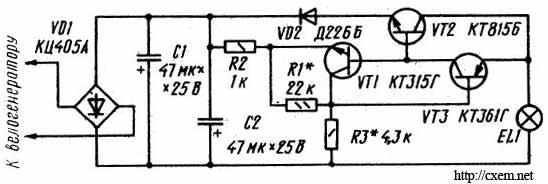
Alternating the tension on the bridge comes from Wellenreiter. When Wellenreiter the output voltage of the diode bridge may vary within wide limits, but the output of the stabilizer (i.e. on the findings of the EL lamp.1 of the bike lights) it does not exceed the maximum allowable voltage bulbs (3.5 V or 6 V, - depending on the lamp and the resistance of the resistor R3). Also indicated in the diagram, you can use transistors CTA-CTV, CTA-CTI, any of a series of CT (VT1); CTA-CTG, CTA-CTG, CTA, CTB (VT3); CTA-CTD, any of a series of CT (VT3). Diode bridge VD1 - any of a series of KTS405, diode VD2 - anyone with a valid rectified current is not less than 0.3 A.
The establishment of the stabilizer is reduced to the selection of the resistor R3 with such resistance that the voltage across the lamp does not exceed the permissible (3.5 V or 6 V, - depending on the lamp used) even at the maximum voltage of Wellenreiter. It should be noted that this scheme has the following disadvantages: in the stabilizer of the large voltage drop across the diode bridge VD1,the diode VD2, the emitter transition VT2, whereby to obtain the output naprajenniy stabilizer 3.5 V to the diode bridge must be received from Wellenreiter about 7 V. this requires a faster drive.
Publication: www.cxem.net