In assessing the state of cardiovascular system of modern medicine and biology widely used technique is the so-called impedance realtystore (recording the changes of electrical conductivity of the human body). Realtystore used in the study of Central and peripheral blood circulation. The advantage of this method is that the study itself practically does not change the state of the object.
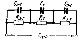
The electrical resistance between any parts of the human body is a complex bulk resistance, a simplified circuit equivalent to that for AC is shown in Fig. 1.
The capacity of the Fe-t occurs between the surfaces of the electrodes and the tissues adjacent to the inner side of the skin. The skin, especially the epithelium, has a very high resistivity and represents the dielectric of the capacitors Se-T. Tissue lying under the skin, conditionally accepted .homogeneous structure. They are presented in the form of CT and RT. The capacitance of the Fe-t depend on the dielectric properties of the skin, its condition (e.g. moisture) and the area of superimposed electrodes.

Fig.1
The value of the capacitance is determined by the polarization of affect, which decreases with increasing frequency. At frequencies above 80 Hz to 100 kHz, the polarization phenomenon is practically not observed, and the capacitive reactance of the capacitor CT is small. We can assume, therefore, that the conductivity of the tissue in the area of these frequencies has the only active component.
The absolute value of the resistance of living tissue is unstable, and depend on a number of reasons, which are often difficult to consider. As a consequence of interest. not the absolute values of the resistance and its relative change from any initial level.
At the present time can be considered proven that the electrical conductivity of living tissue is determined mainly by the extent of its blood supply. This is because the blood (mainly her plasma) has a very high conductivity. Therefore, the electrical conductivity of the living tissue at high frequencies it is possible to judge perfusion of individual organs or body parts. The research technique is called realtystore, and sometimes just by impedance plethysmography.
Described below is a device called reopletizmografiy, is suitable for quick research minor changes the conductivity of living tissues, reflecting the pulse oscillation of blood supply and slow (from 0 Hz) changes in blood supply, e.g., breathing. Realtystore is a portable console transistors to a cardiograph (write pulse fluctuations of blood supply). With the release of this console, the voltage can be feed to a recorder (e.g., N).
The operating frequency of 150 kHz. The output voltage is not less than 2 mV when the resistance is 50 ohms. 0.1%. The frequency ranges of the output voltage from the output of 1-4 0.2 to 150 Hz and the output from the 2-3 0-150 Hz.
Schematic diagram
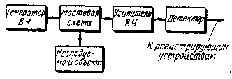
The principle of operation reopletizmografa is illustrated in the block diagram (Fig. 2). The analyzed portion of living tissue connected to one arm of the bridge, fed by alternating current with frequency of 150 kHz. The bridge is balanced so that the RF voltage on the diagonal of the screen was minimal.

Fig.2
Changes the conductivity of the investigated object lead to modulation of the RF voltage at the output of the bridge according to the law of change of the electrical conductivity of the object. Modulated RF voltage is amplified and detected. As a result of detection of secreted modulating the LF voltage, which is supplied to the recording device.
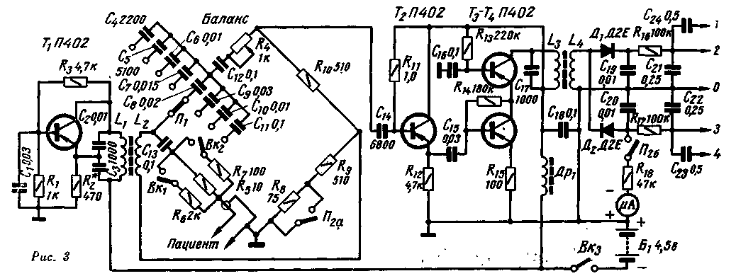
Schematic diagram reopletizmografa shown in Fig. 3. The RF generator is performed on the transistor T1 in the circuit with capacitive feedback. Oscillation circuit included in the collector circuit of the transistor, its resonant frequency is determined by the inductance of the coil L1 and the total capacitance of the capacitors C2 - C3. Depth positive feedback depends on the ratio of the capacitors C2-C3 and resistor R2. The transistor base is grounded AC-coupled (via capacitor C1).

Fig.3
Generator, assembled on the circuit, has a high frequency stability, the design of its contour coils simple and the building is not difficult, because you don't have to pick up the order of inclusion of the findings of the coils.
With the coil L1 of the high-frequency voltage is applied to the measuring bridge. In the left, lower on the scheme, the shoulder of the bridge in series with the elements С13R5-R7 using a shielded cable connects the object (marked on the diagram "Patient"), With potentiometer R4 ("Balance") you can balance the bridge by the active component, and through capacitor C4 to C11 - reactive component.
In real conditions is always observed as a fast (pulse) fluctuation conductivity and slow, such as that caused by breathing. The amplitude of slow oscillations as a rule, considerably greater than the pulse amplitude of oscillation. If you work in conditions of exact balance of the bridge, slow swing changes can lead to an imbalance that, in turn, will lead to a phase change of the output voltage. Therefore, when the balancing switch P2 is set at a position at which the resistor R8 zamorachivatsja, and the balance indicator (ammeter) is connected to the output of the detector.
The research results can be obtained numerically. With this purpose, consistently with the "Patient" (and sometimes parallel to it) include the potentiometer, changing the resistance of which to calibrate the sensitivity of the entire path of the device. Most often used the following calibration method: when changing the resistance in the circuit "Patient" 0.05 Ohm recording amplitude should be 1 cm to exclude the influence of transient resistance of contacts is used, the calibration scheme shown in Fig.3. Consistently with the "Patient resistor R5, in parallel to which the switch VC connects the resistor R6, the resistance of which is 200 times larger than R5. However, their total resistance of 0.05 Ohm less than R5. During calibration prior to the recording of slow oscillations parallel to R5 connects the resistor R7. Then the total circuit resistance decreases by 1 Ohm.
The voltage from the bridge is fed to the emitter follower assembled on the transistor T2, and then the two-stage amplifier, made by cascadei scheme. The load of the amplifier circuit is L3C17, tuned to a frequency of 150 kHz.
Detector based on semiconductor diodes D1 - D2.As a result of using full-wave detector console has balanced out. Constant-time bit detector circuits are selected such that, after detection of the allocated components of the signal with frequencies up to 150 Hz. From the low frequency time constant determined by the capacitance transient of the capacitors C21 and C22 and input impedance of the subsequent stages. With an input resistance of 1 Mω, the lower frequency boundary of approximately 0.2 Hz at - 3 dB.
To the output of the detector is connected microammeter, minimum deflection which balance the bridge before starting the measurement.
Design and details
Realtystore made in a rectangular metallic casing with exterior dimensions HH mm. All the details of it, except power supplies, are mounted on the circuit boards attached to the top cover, which is both a front panel. The front panel includes: ammeter, switches BK1 - BK3, switches P1, P2 and a connector for connecting the cable to the Patient. A connector to connect the device to the registering devices located on the rear panel. All the details reopletizmografa are mounted on two circuit boards. One placed at the screen from sheet metal, is mounted generator, on the other amplifier, the detector and the measuring bridge.
The device uses transistors having in the range of 30-50. Contour coil is made on the cores of type SB-2A, coiled wire sew 0.1 and contain: coil L1-200 turns, the coil L2 is 80 turns, the coil L3 is 200 turns and the coil L4 - 100 turns.
Choke DR1 wound on a ferrite ring f-600, the outer diameter of 12 mm, and contains 200 turns of wire sew 0,1.
Resistor R4 must be a wire, and a resistor R5 is made up of three parallel connected resistors and 91 27,27 Ohm. As an indicator you can apply any microammeter, whose sensitivity 50 - 200 mA.
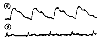
Examples of recordings obtained with the described reopletizmografiy, shown in Fig. 4.

Fig.4
Authors: Vladimir Bolshov, V. Smirnov; Publication: N. Bolshakov, rf.atnn.ru


