Laser pointers, which appeared in recently on the market are designed primarily for teachers educational institutions to use them for their graphic explanations materials. However, such a pointer can be used in the home, say, for remote control operation of electric and radio devices. How this exercise is described in a published article. Laser pointer, despite its apparent simplicity, a relatively complex product. It contains the semiconductor laser, the automatic maintenance of a specified current flowing through it, the optical system, the galvanic battery the cell voltage of 3...4.5 V, the power button.
Consumed by the laser current is 30... 50 mA. Although emitted from pointer power (length waves...650 630 nm) does not exceed 5 mW, due to the concentration in her a narrow beam loss on the spread is small. Radiation laser can be locked at a great distance. However, categorically not allowed to direct the beam pointer is dangerous. Pointer can to work in security devices, sweetleaf, homemade toys, devices scaring away birds etc but for now let's limit ourselves to the story of the construction of the machine according to the pointer signal to turn on and off household electrical and radio devices. The pointer in this case, no alteration is not required.

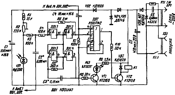
Fig. 1
Machine (Fig. 1) comprises a photodetector on the photodiode VD1, the voltage comparator logic elements DD1.1, DD1.2, the pulse generator on the elements DD1.3, DD1.4, D-flip-flop DD2, two electronic key on transistors VT1, VT2, the Executive element - electromagnetic relay K1 and the power supply. The power supply is made by the transformerless circuit with damping capacitor Coll. The AC voltage is rectified by diodes VD6, VD7, smoothed by capacitor C5 and is stabilized by Zener diodes VD4, VD5. Power to the chip is supplied with the Zener diode through the diode VD4 VD2 and the smoothing capacitor C 1.
Device works well. In the initial time, after you connect the device to the network, a logic high level through a chain C4R7 is fed to the input R of the flip-flop and resets it. On the trigger output is a logic low, the key on the transistor VT2 is closed, the relay is de-energized, the load is disconnected from the network. Input and output the comparator will be logic high, and the inputs of the elements DD1.3, DD1.4 - low, the generator is not working. Thus at the exit of the element DD1.4 established a high level, the transistor VT1 is opened and includes led HL1.
How is the switch? Photodiode VD1 light a laser beam, and the voltage across it decreases significantly. The comparator after the discharge of the capacitor C2 is triggered, and its output appears low level. The conclusions on the elements DD1.3, DD1.4 goes to a high level, the generator starts, the led flashes, indicating that the illumination of the photodiode. If you now turn off the laser or remove the beam in the side of the photodiode, the voltage across it will increase, the comparator will be set in position with high level output, and a trigger switches. Its output will appear high logic level, the VT2 transistor opens, and the relay will close the contacts K1.1 served on the load network voltage. In the case of repeated intermittent illumination of the photodiode (until the led will flash) the unit switches to the initial state and the load abastecida.
Through the use of relays to the device valid connect a variety of electronic equipment: radios, TVs, VCRs, etc. with any blocks power and electrical devices with motors, such as fans.

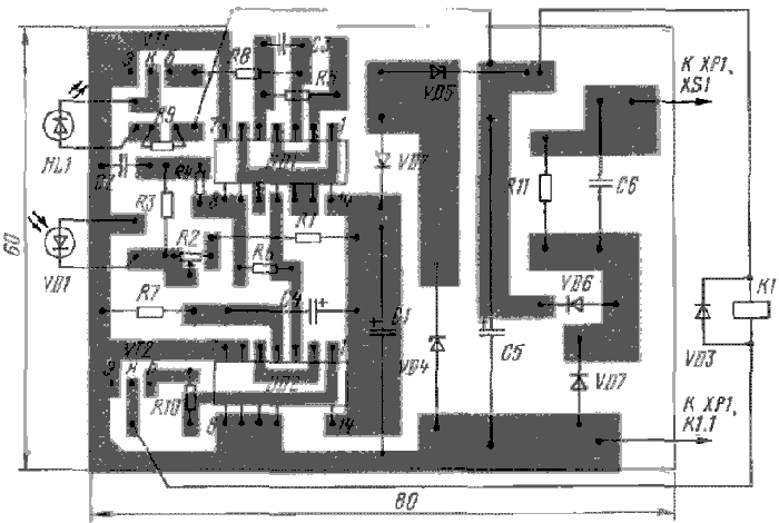
Fig. 2
All parts of the device except the relay and diode VD3, post on the circuit Board (Fig. 2) of one-sided glass fiberglass. It is designed for use transistors CTA-CTA, CTA-CTV, CTA-CTD, chip series To 176, K, 564, any LEDs from the AL307 (preferably in plastic the casing). Diodes VD2, VD3 - any rectifier, VD6, VD7 - KD102B or similar low-power with a maximum reverse voltage less than 400 V and a current not less than 100 mA, the Zener - voltage stabilization 8...10 V. Polar capacitors - series K50, K52, C6 - K73, rest km, KLS, To 10. The trimmer R2 - SDR-19, permanent - MLT, S2-33. The relay should be selected with a voltage tripping 12... 15 V at a current of 30 mA, for example RES9 (passport RS4.524.200, RS4.524.201), the contacts must withstand the voltage and the current consumed by the load.
A few words about the relay RES. On reference data the contacts are designed for a voltage of 115 V. However, long-term practice of using relays in various devices showed reliable operation of the contacts when the network voltage of 220 V. of Course, you can stop the selection of relay types LV, MCM-48, but the size of the structure will increase significantly.
Charge together with the relay placed in the housing of suitable dimensions, made of insulating material. Photodiode and the led fitted in the holes next to the led served the benchmark and its flashes signaled the penetration of the laser beam on the photodiode. To avoid interference and malfunctions, you need to install machine, so that the photodiode was protected from the ingress of light from lighting devices. Establishing device is reduced to the setting of the sensitivity (trimming resistor R2), the speed of response to illumination by the laser (the selection of the capacitor C2), the flashing frequency of the led (rough - selection of capacitor NW, sliding resistor R5).
The machine can be somewhat simplified by eliminating the generator. The left circuit output resistor R8 should be removed from the pin 3 of the chip DD1 and connect with the pin 11. Elements R5, NW is removed, the connection between pins 2 and 4 DD1 clean, and unused inputs of the elements DD1.3, DD1.4 connect the common wire. In this case, when hit by the laser beam on the photodiode and the triggering of the comparator, the led will extinguish.

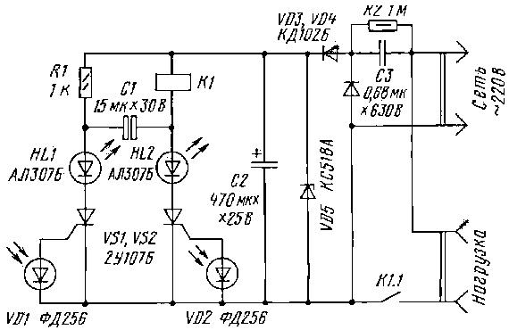
Fig. 3
The variant more simple machine (Fig. 3) if it use a sensitive triacs UA-UE that open for small (less volts) the voltage at the control the electrode and a small (a few microamperes) the current in its circuit. It is the trigger the triacs VS1.VS2 fed, as in the previous design of the block with the quenching capacitor. Analyze the operation of the machine. After connecting to the network both SCR will be closed, and the relay is deenergized.
If you light the photodiode VD2 laser beam, due to the photoelectric effect as shown by the voltage that will go on the control electrode of SCR VS2 and it will open. The relay will go off and will include the load in the network - this will signal the lightened led HL2. Will begin charging the capacitor C1 (the minus on the right under the scheme the derivation). To disable the load light photodiode VD1. In this case SCR VS1 open, including led HL1. SCR VS2 is closed, since its anode momentarily goes negative the voltage of the capacitor C1. The relay is de-energized, the led HL2 is off, the load is disconnected from the network.
If you again illuminate the photodiode VD2, open SCR VS2, a VS1 is closed, since its anode goes the negative voltage from the capacitor C1. The load will go voltage. The experiments showed that the photodiode in this the machine work well LEDs ALA, ALB as their basis are light emitting diodes IR range. In addition, they are equipped with the focusing reflector, which increases their sensitivity to laser radiation pointer.

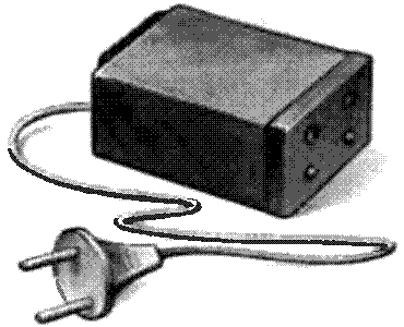
Fig. 4
Details machine is designed to work with the relay RES (passport RS4.524.200). They can be placed in the housing of small dimensions (Fig. 4) made of insulating material. On the front wall of the drilled hole LEDs and photodiodes, the rear install a wall outlet.
When establishing automatic pre-select the capacitor and NW the Zener diode. Voltage is the Zener voltage should be about 4...5 In more voltage relay, and the capacitance of the capacitor, to ensure the current through the relay 15...20 mA more current it positives. The disadvantage of this machine is its low sensitivity, limiting the range of its management. When establishing the machine you must comply with electrical safety measures, because its details galvanically connected to the network. All soldering should be done only when unplugged the machine.
Author: I. Nechaev, Kursk; Publication: www.cxem.net


