


")

The basis of operation of the device based on the dependence of the voltage drop across the p-n switching silicon diode temperature while flowing through it a fixed direct current. It decreases linearly to 2…2.5 mV with each the degree of increase of temperature in the range -60…+120 °C. the Thermometer circuit of which is shown in Fig. 1 represents, in essence, millivoltmeter DC. In it adopted a number of measures that reduce the impact of changes in temperature elements (except the sensor - diode VD1 on the readings.
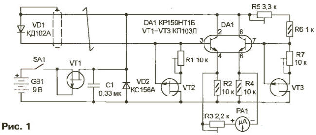
The sensor current is stable transistor VT2 working in thermostable point the output characteristics (the stabilizing current of approximately 200 μa). Similar the transistor VT3 is stable, the current in the circuit formation model voltage. Both transistor circuits DA1 reside on a single semiconductor the crystal and have the same parameters, the same temperature-dependent. In indication of the microammeter RA1 depend only on the temperature sensor.
On the VT1 transistor and the Zener diode VD2 is assembled stabilizer voltage thermometer. The drain current of the transistor VT1 is equal to approximately 3.5 mA at the change of supply voltage in the range 8… 12 V. This further improves the stability of the output voltage of the stabilizer and the readings.
The device collect surface-mount, small textolite Board. It can to strengthen directly on the screws-the findings of the microammeter RA1 - M42304 with a zero mark in the middle of the scale. It is convenient to choose microammeter thus, to current full deflection his hands in µa match the necessary interval of the measured temperature in degrees Celsius. Then, not changing numbers on the scale, it helps to correct the there unit of measurement.
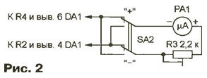
You can use ordinary microammeter (with zero at the beginning of the scale), connecting it according to the scheme shown in Fig. 2. But with the change in the sign of the measured temperature have to switch SA2 to the appropriate position.
Transistors QPL can be replaced by CPI. If possible, as VT2 and VT3 need to use matched at the factory transistors with similar parameters. To the designation of such transistors is added to the index R (KER, KPLR) and put them in pairs in a common package. Chip CRT can be replaced integral switch CKT containing two transistors with common collector, or its imported counterpart X. In the extreme case can to use two separate transistors, for example, with any KT3102 letter index, but to achieve a high stability of the device when it is unlikely succeed. However, such a solution is acceptable, if the measuring part of the device will be kept indoors with a relatively stable temperature. In this situation, you can go for even more simplification, replacing the chain VT2R1 and VT3R7 same constant resistor 100 Ohm.
Diode VD1 place where temperature control is needed. Length shielded twisted pair of wires connecting the sensor to the device may to reach five meters or more. To eliminate interference caused by the detection high-frequency signals of nearby radio and television stations, diode sensor useful shall be shorted ceramic capacitor of at least 0.1 UF. Except as described in scheme CDA as a sensor suit and other small silicon diodes. Experience shows that the reaction rate at the temperature change is higher the smaller the size of the diode and thinner than its conclusions.
Getting to the establishment of the thermometer, first of all we should find the thermostable the operating points of transistors VT2 and VT3. Remember, careless execution of these operations will lead to incorrect operation of the device. To adjust the stabilizer current on the VT2 transistor in series with the diode VD1 or instead include microammeter (fit any of the common digital multimeters) and a trimming resistor R1 will set the current of approximately 200 µa. Alternately heating the transistor soldering and cooling it with cotton wool soaked acetone, choose the position of the slider of the resistor R1, whereby the current through the sensor does not depend on the temperature of the transistor. Similarly, incorporating microammeter in the open circuit R5R6, are heat-stable operating point transistor VT3, adjusting the current of the trimming resistor R7.
Before proceeding to the calibration scale of the instrument must be protected from moisture diode-sensor VD1 and place soldering the connecting wires to it. Protected areas cover any acid-free sealant. The compositions of the acid-based (their distinguished by the characteristic smell of vinegar) in this case is unusable, as corrode thin the outputs of the diode and have significant electrical conductivity. Neat sealing will protect the sensor from harmful influences and in the process of operation, only slightly increasing its thermal inertia.
For calibration you will need a vessel with melting ice and heating device with boiling, preferably distilled water. The sensor is immersed in melting ice, trying to place it as close as possible to the border of water-ice. Trimmer resistor R5 achieve zero readings microammeter RA1. Carry sensor in the boiling water and a trimming resistor R3 sets the arrow microammeter on the point of +100 °C. These operations it is useful to repeat a few time, correcting if necessary, the provisions of the engines of trimming resistors. Additional control point can be temperature of the human body (+36,6 °C), which, if necessary, easily be clarified with the help of medical thermometer.
Author: S. Gantz, Gubkinsky, Yamal-Nenets Autonomous district