


")

When developing thermal stabilizers with a triac as a switching the heater element is necessary to pay great attention to the insulation of the measuring the circuit from the mains. Most often this is in the control circuit of the triac set the optocoupler, and the site of temperature measurement is fed through a step transformer operating at a frequency of 50 Hz. The author offers original the solution to the problem, which allows to dispense coupler and mains transformer and significantly reduce the weight and size of the device.
Thermal stabilizer, assembled according to the scheme shown in the figure, can be roughly be divided into two parts: galvanically connected with the network management node the triac VS1 (DD1 chip, transistors VT1, VT2, VT4), commuting the heater and the node of the sensor (thermistor RK1, DA1 chip, transistor VT3), isolated from the mains-frequency transformer T1.
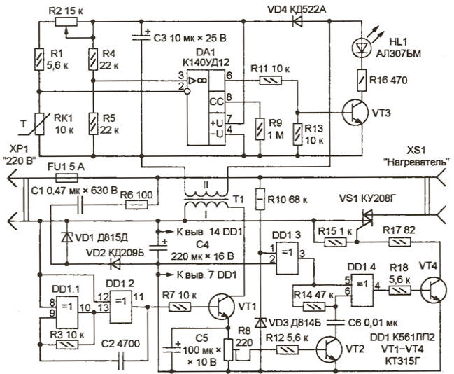
A control unit triac receives a supply voltage half-wave rectifier with "extinguishing" the capacitor C1. Rectified voltage stabilized by the Zener diode VD1. On the elements DD1.1, DD1.2 assembled generator pulses of a frequency of about 10 kHz. Cascade transistor VT1 - amplifier pulse transformer load. Its feature is the dependence of the fall the voltage across the resistor R8 from the resistance, which loaded the secondary winding the transformer T1. Therefore closed in the absence of the load transistor VT2 opens with consumption growth from current winding II.
The Zener diode VD3 with damping resistor R10 and the element DD1.3 form rectangular pulses, fronts and troughs coincide with the moments of transition network voltage through zero. When closed, the transistor VT2 circuit of the capacitor C6 open, to both inputs of the element DD1.4 receive the same signal and level at the output of the element is low. The transistor VT4, and with it the triac VS1 closed. On plugged XS1 heater mains voltage is not supplied.
When the transistor VT2 is open, integrated circuit R14C6 slightly delays the pulses received at the input 6 DD1.4, resulting in the output of this item appear the pulses of approximately 0.3 MS, coinciding with the crossings of the mains voltage through zero. After passing the amplifier transistor VT4, the pulses at the beginning of each half cycle of the open triac VS1. Heater connected to the network.
Thus it is possible to control the heater by altering the load connected to the network isolated winding II of the transformer T1. Rectified using a diode VD4 voltage of this winding is fed OU DA1 and the resistive bridge, one of the shoulders where is the thermistor RK1. Temperature-dependent voltage imbalance of the bridge is fed to the inputs of the op amp. As a result, when the temperature is below a predetermined voltage level at the output DA1 is high and above the preset is low. Temperature threshold set by the variable resistor R2.
Itself the change of the voltage level at the output DA1 cannot lead to the opening of the triac VS1, since the current consumption of the shelter (approximately 1.4 mA), almost does not change. Role variable load performs the cascade transistor VT3 with HL1 led in the collector circuit. If the temperature is below the threshold, VT3 transistor is open, the led is lit, and the consumption current increases to 7 mA. Proportionally increases the voltage drop across the resistor R8 in emitter circuit of the transistor VT1, which leads to the heater.
The magnetic core of the transformer T1 - steel SSH, winding I - 600, II - 1000 turns of wire sew-2 0,08. Special attention should be paid to insulation, paving between windings two or three layers of varnished cloth and soaking the finished coil or paraffin moisture-proof varnish. The thermistor RK1 - MMT-4. The Zener diode VD1 can be replaced CSA, and as VD3 use with any low voltage stabilization 7…9 V. the Capacitor C1 - K73-17 or similar on the operating voltage not specified below in the diagram. Other parts - General application.
Structurally, the thermal stabilizer can be performed in a single unit, or two separate - control and the temperature sensor, connected by a two wire cable lengths up to several meters. The last option is more convenient for large rooms (vegetable stores, greenhouses, where the temperature sensor has stand at a considerable distance.
At the time of adjustment to the socket XS1 instead of the heater it is better to connect to a standard a bulb that will allow you to visually monitor the operation of the device. Adjusting the control of the triac is to install the engine trimmer potentiometer R8 in a position so that the voltage at it was not less than 0.8 V when the led is lit HL1, and not more than 0.3 V in if it is not.
For calibration of the scale of the variable resistor R2 can not connect the heat stabilizer to the network. The sensor node is detached from the winding II of the transformer T1 and fed from the DC power supply 9…12 (plus - to the anodes diode VD4 and LEDs HL1, minus connects to pin 4 of the chip DA1). Thermistor RK1 placed in an environment with a known temperature (monitored by conventional laboratory thermometer). Slowly rotating axis of the variable resistor, fixed the moment of ignition or extinction of the led HL1 and do at the appropriate scale mark. The procedure is repeated at several different temperatures. Listed on the scheme resistor values R1 and R2 correspond to the temperature interval from about 0 to 40 °C. by Changing the resistor values, you can move these boundaries in the desired side. After finishing the calibration, the sensor is connected back to the transformer T1.
Author: S. Bazylev, Shebekino, Belgorod region.