The device is intended to control active power of the load, the author has used feedback not only to stabilize the output voltage, but for the limitation of the pulse duration, opening the triac.
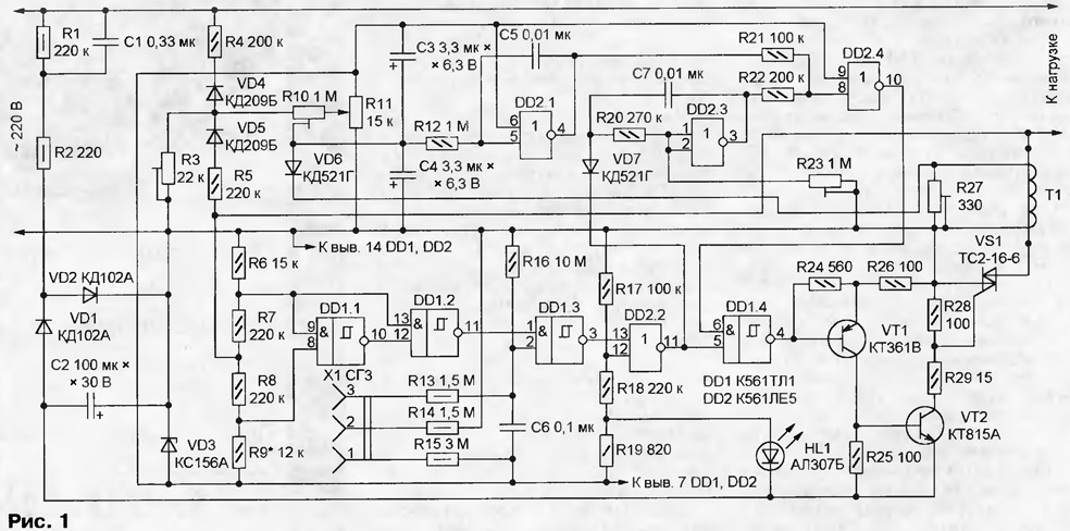
The control circuit shown in Fig. 1. Included in the load circuit of the triac VS1 manages the electronic key on transistors VT1 and VT2. Opening voltage is supplied to the control electrode of the triac, if the logic level at the output element DD1.4 low.

(click to enlarge)
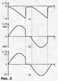
The integrator on the element DD2.3, operating in linear mode, linear forms the falling voltage (Fig. 2A), which through resistors R21, R22 added to the feedback voltage, the amount fed to the input element DD2.4. Once it becomes less than the switching threshold of this element, its the output appears high, and at the exit of the element DD1.4 is a logic low, that will lead to the opening of the triac VS1.

The node of the resistors R6 - R9 and logic elements DD1.1, DD1.2 controls the voltage across the triac, the waveform of which is shown in Fig. 2,b. If the absolute value of this voltage is less than the predetermined value, Boolean the level at the exit of the element DD1.2 low, otherwise high. "Positive" and "negative" threshold level, selecting a resistor R9. So as the voltage drop across the opened triac VS1 close to zero, low output level DD1.2 chain DD1.3 - DD2.2 - DD1.4 - VT1 - VT2 leads to the cessation of current in the circuit of the control electrode of the triac. As a result the pulse width of this electrode is only slightly higher than the minimum, - opening of the triac.
At the same time the low level at the output of the element DD2.2 through the diode VD7 sets in the initial state of the sawtooth generator on the element DD2.3. A new cycle of operation of the generator will start when the voltage on the triac will change the polarity and exceeds a threshold control node.
Another function of this node is to stop the supply to the triac opens pulses, if disconnected from the regulator load. This happens automatically since the voltage between the main electrodes of the triac is missing.
On the elements of R3 - R5, VD4, VD5 assembled detector output voltage. The oscillogram of the signal generated at the resistor R3 shown in Fig. 2, V. It the DC component is proportional to the mean straightened voltage value at the load. In a proportion, based on the location of the engine trimmer R10, the output voltage of the detector is summed with a voltage manual adjustment, coming from the variable resistor R11, and filtered using capacitors C3 and C4. Loop negative feedback voltage is shorted through the amplifier on the element DD2.1 operating in a linear mode. Capacitor C5 serves to additional filtering.
In series in the load circuit included the primary winding of the current transformer T1. The voltage drop across the resistor R27, shunting the secondary winding the transformer is proportional to the current load. When its instantaneous value at absolute value is larger than the engine tuning resistor R10, diode VD6 opens and chain adjustment signal that reduces the output voltage.
Socket X1 connect to the controller external switch, for example, a contact thermometer. Circuit sockets 1 and 3 sockets sets low the logic level at the input 2 of the element DD1.3 that blocks the opening of the triac and leads to load loss. Protective resistors R13 - R15 to limit safe value the current flowing through the external control circuits. Capacitor C6 protects against interference.
The node power controller consists of the quenching capacitor C1 shunted resistor R1 limiting resistor R2 and rectifier diodes VD1, VD2 with storage capacitor C2. The output voltage of the rectifier is approximately 16 In - directly is only used to power the control circuits the triac VS1. Rest of the nodes of the voltage regulator is stable Zener diode VD3.
After submission of the line voltage resistive divider supports on R17R18 the inlet 12 of the element DD2.2 high logic level as long as the capacitor C2 has charged to approximately 10 V. This prohibits false opening triac until the beginning of normal operation of the regulator.
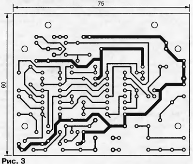
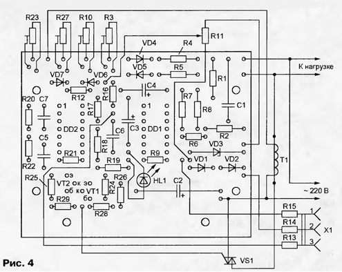
The regulator is assembled in body size 135x85x50 mm of aluminum alloy. On the housings are equipped with three-prong plug and a similar outlet for connection to the load. Earthing contact plug and socket are electrically connected to the housing. Almost all the details of the regulator are mounted on inside the enclosure the PCB size 75x60 mm of one-sided foil fiberglass. The drawing Board with the printed conductors shown in Fig. 3, the arrangement of elements by their installation in Fig. 4.


Triac VS1 mounted on aluminum corner, the second "shelf" where the thickness of 5 mm has a reliable thermal contact with the housing of the regulator, but electrically isolated from it by a strip of polyimide film having a thickness of 0.05 mm, oiled with both sides heat-conducting paste. The quality of insulation should be checked testers with a test voltage of at least 1000 V.
The magnetic circuit of the transformer T1 is constructed from two "half-rings" from standard SLH. Primary winding serves as a main lead, missed the window of the magnetic core, the secondary winding of 1000 turns of enameled wire diameter 0.1 mm. In the manufacture of the transformer, you can use the recommendations from article I. Nechaeva "Indicator power" ("Radio", 2000, № 11, p. 59).
Variable resistor R11 and socket X1 installed on the bracket, mounted on a printed circuit Board. Resistors R13 - R15 one soldered directly to the output contacts of sockets X1 and protected PVC insulation tubes. The second terminals of resistors connected to respective contact pads on Board.
Resistor R16 - C3-14, remaining constant - MLT set - SDR-19a. Variable resistor R11 - SDR-9 or PPV-40 on the axis of the handle is put on the insulating material. Capacitor C1 - K73-17 630, C5, C6 - ceramic K10-17, km or film, C7 - series K73 or ceramic band TKE's not worse M1500. Oxide capacitors - K53-18 for a voltage of less than 16 In (C2) and 6.3 In (C3, C4). You can apply oxide capacitors of other types, including aluminum K50-35. In the latter case will have to change the location of some contact pads and conductors on the circuit Board. Diodes VD1, VD2, VD6, VD7 - series CD or KD522, the Zener diode VD3 - domestic production or import for voltage stabilization of 5.6 V. the Diodes VD4, VD5 should be designed for reverse voltage not less than 400 V, for example, CD, with CD any alphabetic indices. The led may be any operating at up to 15 mA. Transistor VT1 can be series KT361 (with indices A, b - E), CT (A - D, AND K), CT (G - M), CTB; VT2 - KT815, CT with any letter indices or CTB.
As a replacement chip DD1 suitable CLA, but to achieve symmetry the output voltage may require the selection of resistor R9. The triac needs to have a class a voltage no lower than fourth. Except as described in the diagram test the functionality of the triac TC 112-10 and TS-80.
Getting to the establishment of the regulator, the engines set of trimming resistors in the following scheme (see Fig. 1): R10 - right, R3 - in the middle, R11 in the upper part. Connected to the output load - incandescent lamp 100-W - and AC voltmeter. For greater security when establishing a it is recommended to connect the controller to the network so that the total wire (the positive lead of the capacitor C2) was connected to the neutral wire of the network. Rotate the axis of trimming resistors need a screwdriver with a handle of insulating material.
Under above mentioned position of adjustment of the triac is closed, the voltage on the load is absent, HL1 led is lit, indicating that the controller is connected to the network. The rotating axis of the tuning resistor R23, the control signal at the output element DD2.3 with an oscilloscope. The minimum value of the sawtooth voltage should be 0.4...0.6 V above the voltage on the findings of the 7 circuits DD1 and DD2.
If no oscilloscope, analog DC voltmeter measure the voltage supply circuits between pins 7 and 14 of one of them. Then include voltmeter between pins 3 and 14 of the chip DD2 and resistor R23 achieve it readings in the range of 40...45% of the previously measured voltage.
Trimmer R10 set lower, then R3 - upper limits regulation of the output voltage. Briefly connecting to the controller the load capacity of a little more valid in continuous operation, set the engine tuning resistor R27 to the position at which the set the output voltage starts to decrease. Permissible load current depending on the type applied triac and in the present case must not exceed 10 A.
Author: A. Abramsky, Novosibirsk


