


")

Power control (RM) load or chemnical" provides automatic changing the power input to the light load, up to various specified levels. The values of the upper and lower levels, and the transition between them specifies the user. RM allows you to not only set a comfortable level lighting and halls, but also to realize stepless its inclusion within given time, and also to increase the lifespan of incandescent bulbs.
Control device with buttons and a three digit indicator. The RM can to work in both manual and automatic mode. In the first case, choose the desired brightness of the lamp by increasing or decreasing supplied to them power in 5% increments, and the second controller automatically changes smoothly the output power at a predetermined interval for a predetermined time. Boundary the values of the power levels chosen in the range 0…99% (in increments of 5%, the latter 4%). and the time interval of transition between them in the range 0…60 C (from step 5).
RM can be used to serve not only light, but also other active network load (for example, heaters of various types, including soldering irons etc.).
Main technical parameters: power supply voltage -220 ±20%; supply current - 60 mA; the interval of temperatures from 0 to +60°C.
The maximum value of the load current and a limit value switching capacity use determine the triac and heat sink.
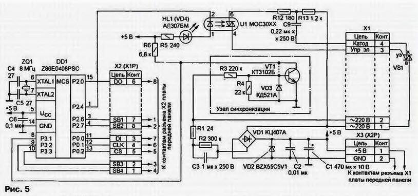
The basis of RM - two microcontrollers. One of them is the main or leading pair located on a modified pay-PU (Fig. 5), described in "Radio", No. 7.
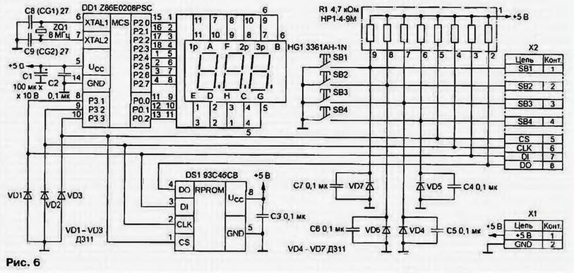
It there are a number of contacts x2 (HR) for connection via serial interface SPI slave device, in which the controller performs front fee panels (Fig. 6). It is located on the second (slave) microcontroller pairs with DD1 castorocauda circuit similar to that used in the previously described constructions, as well as the three digit indicator HG1, buttons SB1 - SB4 and chip DS1 non-volatile memory. The presence of the indicator and buttons simplifies mode selection work and non-volatile memory stores the selected mode after disconnection power the device.
The main microcontroller couples caters to the button and the node non-volatile memory, generates control signals for the power circuit switching device, and generates information codes for CPU indicator. The second microcontroller operates synchronously with the first and is only responsible for converting it information codes in the dynamic pulse control digital indicator.
Microcontrollers RM feed from omednennaja transformerless source PU, in where the capacitance of the capacitor C3 is increased to 1 μf, and the resistance of the resistor R1 reduced to 24 Ohms. As DD1 used a more powerful microcontroller Z86E0408PSC. In addition, PU Board in this application installs vosmichastny (instead of six) connector x2 (HR), ports P2.6. P2.7, eliminate the resistors R7, R8 (their functions are performed by the resistor R1 Board front panel), triac VS1 and chain VD5C7, VD6C8 (used instead relevant objectives in the front panel Board). The rest of the device, collected to Board PU for the RM, as described in the first part of the article.
To avoid malfunction of the device as a protective diodes VD1 - VD3 port P3 of the microcontroller DD1 (Fig. 6) applied to the diodes with a small direct drop voltage (acceptable use diodes D, D311, or any signal Schottky diodes).
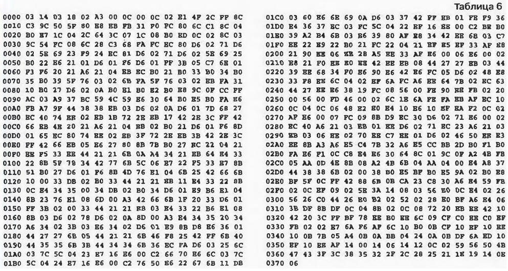
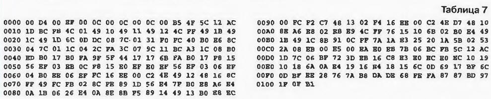
Combining the PU Board and the front panel wires length 200 mm and placing with the triac VS1 and its heat sink in a proper case, obtain finished RM for a certain power. Codes firmware EPROM microcontrollers boards PU and the front panel are shown respectively in table. 6 and 7.
(click to enlarge)
(click to enlarge)
The indicator of the RM can be in one of the following three modes: display installation settings auto mode, correction and indication of the current value power. The first display parameter, and the second and the third its value.
Parameters the parameters are divided into automatic mode and parameters characterizing the current value output device. Parameters automatic mode three: L is the power value of the first (lower) stage, N - the second (upper) stage, t is the time of transition from one to the other.
Parameters characterizing the current value supplied to the power load also three of the initial level (always 0%), u is the capacity of the first (lower) stage, u is the same, the second (upper) stage. The elements of the first category indicator HG1 forming the characters, in bold, are shown in table. 8.
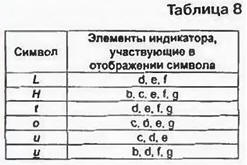
The level value indicator displays either the power level issued to the load (0…99%). either the time interval of a smooth change in automatic mode the output power between the set levels (0…60 C).
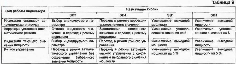
Depending on the type of indicating functions of buttons to control the operation of the device various (table. 9). Thus, the desired parameter in the indication mode select press SB2 to ring: L, N, t, #, L, N,…, where # one of the parameters characterizing the current state of the load (o, u, u). When this in the second and third digits of the display shows the current value settings automatic mode for each parameter (if selected L, N, t) or the current value outputted to the power load (if selected #).
(click to enlarge)
To enter a new value of any of the automatic settings mode should display mode to select the desired (using SB2) and pressing the button SB4 put the device in mode correction value. Confirmation that the device in this mode, is the blinking decimal point the first digit indicator. Change the setting by clicking on SB 1 or SB3: when pressed once first - its value is reduced with a step of 5 units, and if clicking the second one increases with the same step. In conclusion, push the button SB4, and the new value is saved in non-volatile memory device in the quality of the current. If for any reason the result of the correction is necessary to cancel and return to the previous value of the parameter, push the button In SB2 both cases the button is pressed (or SB2 SB4) returns an indicator from this mode correction in the display mode (blinking decimal point the first digit will stop).
For operation of the device in automatic mode to pre-expose corresponding values of the parameters L, H and t in the correction mode. Then use button SB2 switch the meter to display the current value of the output power (o, u, u). Now buttons SB1 and SB3, you can change the current level capacity in accordance with the previously entered settings auto mode (L, N, t).
When developing the automatic transition between the stages of the output power of the second and the third level HG1 flicker to indicate that the process of change. If the light blinks the value of the first stage (u) - navigates to the lower level, and if the second (u) - to the top. Transitions associated with the initial stage (about), always made with "hard" a given maximum allowable speed (50%). It the value is set programmatically with the aim to increase the service life of incandescent lamps for by removing the initial surge. During the transition from the first step to initial always flashes the value of the last (about).
To switch to manual control, the indicator translate (button SB2) mode display the current value of the output power and press the button SB4. About you find it in the manual control mode is evidenced by the blinking of the same decimal point the first digit of the indicator. While using the buttons SB1 and SB3 can respectively reduce and increase the power level at the load with 5% increments. The return to automatic operation by pressing SB2 and confirmed by the cessation of blinking decimal points.
In manual mode you can set (select) the values of the power levels lower (L) and upper (N) levels of automatic operation, focusing directly on the brightness of the load. To do this, transfer the device to the auto mode and use the button SB1 or SB3 choose the output stage power, which requires correction. The device fulfills the yield on the specified power level (L or H). Then use the button SB4 transfer device in the manual mode and the button SB1 or SB3 achieve the desired adjust the power level of the brightness of the load. Then again click the button SB4, and selected in the manual mode, the power value rewritten in the nonvolatile memory cell corresponding to the corrected stage. When the selected value of the current parameter u change the installation the lower level L, and the parameter u is the upper level N. Change the value the initial stage is not.
Authors: A. Olkhovsky, Shcheglov, A. tatevosov, C. Cherniavsky, Moscow