


")

Many hams are known so-called "trigger effect" on the threshold thermal, photoelectric, automatic battery chargers, etc. the Device can work normally dozens of times, but sometimes it is such an unpleasant moment when the actuating relay turns on, it immediately turns off again, etc. This phenomenon can manifest itself for quite a long time - "burn" the relay contacts, and the resource operating time of the relay is not unlimited. If the scheme is applied to the thyristors, with frequent switching on and off they can overheat and fail, and also give interference to the mains supply. In Fig. 1 shows a diagram of the thermostat to the relay, which is such a harmful thing as a "trigger effect", is missing.
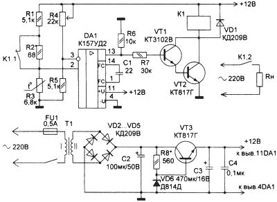
Fig. 1
Assume that the thermostat is used to regulate the temperature of the air in the incubator. If the temperature in the incubator is below +38°C (expose variable resistor R4), the resistance of the thermistor R3 is relatively large and a comparator for DA1 is in positive saturation, the transistors VT1 and VT2 are open, the relay K1 is energized, and heats the air in the incubator. When reaching into the incubator temperature +38°C the resistance of the thermistor R3 becomes smaller and the comparator is thrown into a state of negative saturation (the output potential of the common lead), closed the transistors VT1 and VT2, the relay K1 releases.
Due to the fact that in series with the resistor R1 resistor R2, which is shunted by normally closed contacts of relay K1, the relay is switched on at one temperature and off at another, i.e., maintained at a temperature in the incubator within, for example, +37,5…38°C. the Necessary temperature difference is provided by the selection of resistor R2. Thus, this harmful phenomenon as "the trigger effect", in this scheme, the thermostat is missing. Voltage of the relay K1 should not be below 10 V, the relay contacts must withstand a switched alternating current and can be calculated for a voltage of less than 250 V. the Printed circuit Board of the thermostat shown in Fig. 2.
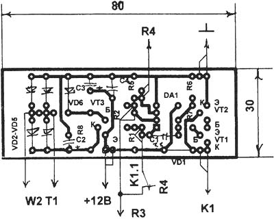
Fig. 2
In Fig. 3 shows a diagram of a temperature regulator with a thyristor in the power section, which is also free from the phenomenon of "trigger effect".
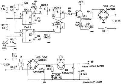
Fig. 3
Assume that the thermostat is also used for incubator, the required temperature must be within +38…39°C (the temperature range exhibiting a variable resistor R4). At the OS chip DA1 performed two-stage comparator. If the temperature in the incubator is below +38°C, the resistance of the thermistor R3 is comparatively large, and both of the comparator are in a state of positive saturation (the level of the log."1" at their outputs). On the logic elements DD1.2, DD1.3 built RS-trigger. If the air temperature in the incubator is below +38°C, at the input S of an RS flip flop is high."0" (inverter after DD1.1) log R - log."1", the trigger is in the "isolated" state (the log."0" on its inverted output 4 DD1.3). In this case, the transistor VT1 is closed, to the control electrode of the thyristor VS1 is supplied with positive potential relative to its cathode, the thyristor is opened, the heating element RL is enabled. When the temperature of the air in the incubator +38°C the resistance of the thermistor R3 is reduced, the comparator on DA1.1 thrown from a condition of positive saturation in a state of negative saturation at the output set log."0", the input S of the flip - flop-log."1", but the trigger remains in a single state, the heating element RH included.
When the air temperature in the incubator reaches the value of +39°C, log."0" will appear on the output of the comparator DA1.2, the input R of an RS flip flop will set it to "zero" state. Thus at pin 4 DD1.3 will log."1", which will open the VT1 transistor, the control electrode of the thyristor VS1 set in a low potential relative to its cathode, the thyristor is closed and the heater is disconnected from the mains. When the air temperature in the incubator is lower than about +39°C, but above +38°C, in a state of positive saturation will set the comparator DA1.2, but the log."1" at input R of the flip-flop does not change its zero state, and the heater will still be disabled. And only when the temperature of the air in the incubator is below +38°C, in a state of positive saturation will set the comparator DA 1.1, the input S of the flip-flop goes the log."0", which will include the work of a heater RL. Thus, the temperature in the incubator is maintained within +38…+39°C (the temperature difference achieved by selection of the resistor R2), and the phenomenon of "trigger effect" in this scheme, the thermostat is missing. The printed circuit Board of the thermostat shown in Fig. 4.
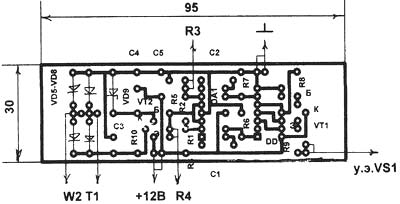
Fig. 4
When establishing and operating the unit you should be careful and not to touch the parts, as in the scheme there is a potential network. It is advisable for a more accurate and smooth adjustment of temperature to choose the variable resistor R4 (and also in the circuit of Fig. 1). Diodes VD1-VD4 can be eliminated. In this case, the heater RL will be only one wave of the mains voltage, i.e. at a power of 500 watts on the heater will stand out 250 watts, and will significantly increase the reliability and durability of the heater. The voltage on the secondary winding of the transformer T1 must be within 16 V. 13…
Author: A. N. Mankovsky, village of Shevchenko, Donetsk oblast; Publication: www.cxem.net