A temperature sensor in the proposed device serves himself... electric heating element whose resistance depends on temperature. Because to install a special sensor is not required, the thermal stabilization is achieved without interfering with the construction of the heating device.
In most electrical appliances used for heating the liquid, ensured good thermal coupling between the heated environment and an electrical heating element. Therefore, maintaining the temperature of the element constant, can be sufficient in many cases to stabilize and accuracy the temperature of the liquid. In some cases, this stabilizer will protect from large trouble. For example, will prevent dangerous overheating of the kettle, included without water or left without supervision, resulting in water boiled away. The proposed device can replace a failed bimetal thermostats in electric irons, where the thermal resistance heater-sole small. This achieves higher accuracy maintain the temperature of the sole. Stabilization of the temperature of the electric heater, working conditions are poor and non-heat-removal (e.g., warming up the air in the room), does not guarantee the constancy of temperature environment, however, increases the reliability and safety of operation of the heater.
Due to the lack of sensor described stabilizer suitable for high temperature heating devices (e.g., muffle furnaces), where eliminates the need to control the temperature with the help of expensive thermocouples.
Diagram of the device shown in Fig. 1.
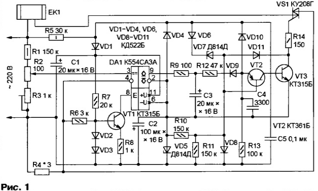
Transistors VT2 and VT3 assembled generator pulse that opens the triac VS1 - switch heater EK1 - in the beginning each half period of the mains voltage. This minimizes switching noise and the power consumed to control the triac. Diodes VD1 and VD4 are rectifiers and Zener diodes VD5 and VD7 - stabilizers voltage comparator DA1 and generator.
The resistance of the heater EK1 forms the resistors R1-R4 of the measuring bridge, the diagonal of which is connected to the inputs of the comparator DA1. Resistance and power resistor R4 should be approximately 0.5 percent of the relevant parameters heater. The voltage drop across this resistor - 1,1...1,2 side.
Using resistors R2 and R3 are making to the bridge is balanced when nominal or maximum (depending on the task to be solved) the temperature of the heater. Analysis of balance occurs when the open triac VS1 and only in the negative half-cycles of the mains voltage, when the transistor VT1 closed negative voltage taken from the resistor R4 than permitted work comparator DA1.
If the temperature and therefore the resistance of the heater defined above, the level at the output of the comparator, if enabled, becomes low. Capacitor C3 is quickly discharged through resistor R9. The emitter of the transistor VT2 through resistor R12 and diode VD9 receives a negative voltage blocking a pulse generator. The generator will resume only after the charging of the capacitor C3 through the resistor R12.
In the near after the resumption of operation of the generator the negative half cycle mains voltage comparator DA1 again check the resistance of the heater EK1, and depending on the result, the generator will either continue to work or re will be blocked. Therefore, if overheated, the voltage at the heater comes only brief intervals, dependent upon the time constant circuit R12C3. If below the predetermined temperature, the heater runs continuously.
When the heater power more than 1 kW it is necessary to replace the triac VS1 specified in the diagram type to a more powerful (for example, series D, TS). To manage therefore the triac may require a current amplifier, assembled according to the scheme it is shown in Fig. 2.
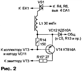
PCB size 40x32,5 mm, shown in scale 2:1 in Fig. 3, is designed exactly for this, amosandy option device. If additional reinforcement is not required, elements VT4, VD12 and R15 not set, and the inductor L1 is replaced by a jumper. Triac VS1 is out fees and must be provided with a heat sink corresponding to the public switched power.
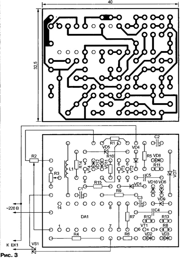
(click to enlarge)
Each of the Zener DD can be replaced by a pair connected in series low-voltage Zener diodes with a total voltage stabilization 12...15 V, for example, XA, XA, XA. Required for such replacement printed the conductors and contact pads shown in Fig. 3 hatched. Role the Zener voltage is approximately 7 In can perform and emitter transitions of transistors KT315B (emitter - cathode, anode equivalent the Zener diode).
Mount everything except the diode VD9, connected to the stabilizer the heater and plug it into the network. First of all check the voltage between terminals 11 and 6 of the comparator DA1, which should be within 24...30 V. If the presence of pulses at the collector of transistor VT3 triac VS1 not opens up or comes off only in the positive half-cycles of the network voltage stabilizer in without additional amplifiers reduce the resistance of the resistor R14. If this method is reliable opening of the triac was not achieved, you will have to install on the cost elements shown in Fig. 2, and a resistor R15.
Further right circuit output resistor R12 temporarily connect a jumper from the "common" wire (for example, with the cathode of the diode VD3) and make sure that using trim resistor R3 can be installed on the capacitor C3 two values voltage: almost close to zero and the voltage stabilizing Zener diode VD5.
Finally adjust the device after removal of the temporary cofferdam and installation diode VD9. Translating variable resistor R2 in one extreme and waited the time required to reach thermal mode, measure the temperature heater or heated environment. The same measurement is repeated at several the position of the handle control resistor R2. According to the obtained results the resistor can be provided with a scale graduated in values of temperature. Border throttle adjust trimpot resistor R3, replacing the need it and variable resistor R2 is similar to another denomination.
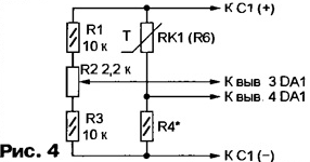
Changing the scheme of the measuring bridge in accordance with Fig. 4 and making some more minor changes on the same printed circuit Board can collect normal the heat stabilizer with temperature sensor - a thermistor.
The portion of the drawing placement of elements for this variant of the device shown in Fig. 5. Everything is beyond, remains the same as in Fig. 3.
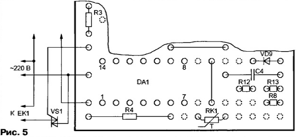
The dotted circles show the holes released from the findings is not needed more elements VT1, VD2, VD3, C3, output from engine tuning (also known now constant) of the resistor R3 and one of the jumper wires. Resistors R7 and R9 are replacing the straps, and pads destined for resistor R6 is connected to the findings of the thermistor RK1 nominal (measured at a temperature of +25 °C) resistance 10. ..100 kω. The value of the resistor R4 choose equal to the resistance of the thermistor RK1 at medium temperature interval regulation.
Author: V. Kaplun, Severodonetsk, Ukraine


