The coolant is water with a high temperature (not lower than 56°C), which used in heating systems for space heating, but also consumed in the apartments and cottages for domestic purposes. The lack of hot water to heat it on household electric and gas stoves, which creates some inconvenience, causes the excessive gas and electricity, the violation of safety. In some cases, you can heat water in simple tanks (boilers), setting in them the heater. Upon reaching the desired temperature of the water in the tank need surgical disconnection of the heater so that water does not boil and not tore the boiler.
Classic water heater made by a simple scheme: the switch outlet and heater. In the best case, they added the pressure sensor and the sensor (regulator) temperature. The pressure sensor protects the boiler against overpressure water, and the temperature sensor is triggered by a temperature increase above a predetermined limit.
As the heater temperature controller is often used bimetal, which differs little from the regulator iron. When reaching preset water temperature, the sensor opens the circuit of heater, temperature water naturally or as a result of consumption and add cold is reduced, and the regulator contacts closed again, including heated. Easy this scheme often leads to malfunction of the heater because of overcooking contacts of the regulator that commute large currents.
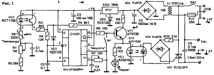
To improve the reliability of the system suggest to use electronic regulator the temperature (Fig.1). It allows you to set the desired temperature of the coolant and keep it in automatic mode.

All sensors are low voltage circuits and galvanically isolated from the mains optocouplers and power transformer. The device consists of:
- temperature sensor (thermistor) RK1 to control and maintain the temperature water;
- opto-line signal amplifier VU1, which allows to increase the sensitivity of the input circuit;
- analog programmable timer on the chip DA1;
- the power amplifier transistor VT1;
- optocoupler VU2 galvanic isolation of control circuits and power circuits heater;
- the control key on the triac VS1;
- power circuits on the transformer T1 and the diode bridge VD3.
Optoelectronic devices provide galvanic isolation of input and output circuits. In the scheme uses two types of optocouplers: VU1 - diode-transistor optocoupler and VU2 - diode-thyristor. The optocoupler have a great gain current, which eliminates the need for additional circuits the gain at the input of the timer and the control circuits of the triac.
The sensitivity of the thermistor (resistance variation with temperature) when use the optocoupler increases with 2...5%/°C up to 12...15%/°C. Diode-transistory optocoupler VU1 and linear mode. Change radiation its led changes the resistance of the collector-emitter internal transistor VU1. which is part of frameshadow timer circuit DA1. Accordingly, changing the charging time of the capacitor C2 of the external circuit timer.
Regulation and set temperature are variable resistors R1 and R7. to maintain any temperature values of thermal parasites. The resistor R1 is set the heating temperature, R7 - heater output. Initial water temperature affects the resistance of the thermistor and, accordingly, for the duration of the positive pulse at the output of the timer. When low coolant temperature pulse duration output max. The integrated timer allows you quite simply have to run the generator pulses. For the chip in the mode of the oscillator pins 2 and 6 are interconnected and are connected to a capacitor C2. In steady mode the interval Tj, during which the timer output valid high the level is determined by the ratio T1=0l69(RVUi+R3)C2. When the inner transistor circuits is opened, the capacitor C2 discharges through resistors R4 and R5, forming second time interval T2 with a low level at the output of DA1. It the duration is determined by the formula: T2=0,69(R4+R5) C2. The value of T2 is not changed from the temperature. The total time of the pulse T is T=T,+T2.
The duty cycle of Q pulses (Q=T/T1) when the temperature increases, the reduces the voltage across the heater and the temperature of the coolant. The frequency generator the timer can be adjusted by changing the voltage at pin 5 DA1. If the voltage is increased frequency of generation of the timer, and power heater is reduced.
The square wave signal output from the DA1 3 through a current limiting resistor R6 is input to the power amplifier transistor VT1. Resistor R8 in the chain of his the collector limits the pulse current through the led of opto-coupler VU2. Application VT1 transistor with high gain allows you to create output signal transistor switch with minimal distortion. This signal is supplied to the led of the optocoupler VU2, enhanced by photodirector and controls the operation power control on the triac VS1. Opening VS1 pulses of both polarities formed by a diode bridge VD4. Optocoupler provides galvanic VU2 isolation of high and low voltage circuits of the device.
If a dinistor optocoupler opened, turning on of the triac occurs in the beginning pauperize mains voltage, when the current through the control electrode reaches the threshold value that reduces the noise level triac Converter.
To improve the accuracy of temperature adjustment, the bridge and the feed timer stabilized voltage regulator from DA2. VD2 diode protects the IC stabilizer from possible reverse breakdown voltage. Capacitors C3 and C5 eliminate the ripple of the rectified voltage, the capacitor C1 removes the noise, occur when adjusting the resistor R1. The Condenser Sat. set in parallel with the load, reduces the noise level triac Converter. The contacts of the pressure sensor P close VT1 base on the body, stopping the heating of emergency coolant pressure in the heater.
The device uses widespread datasheets. Permanent resistors - type MLT-0,125. variables - SP-Ill, a thermistor - MMT-4. Capacitors with oxide - C50-38, high voltage (C6) - K73-17. the remaining km. The timer 555. Transformer power is applied with the voltage of the secondary winding 10...12 V. Switch SA1 - automatic, for a current of 25 A. the pressure Sensor used on the car "the Zhiguli".
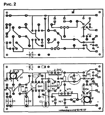
The device is assembled on a printed circuit Board, a drawing of which is shown in Fig.2.

The regulator temperature R1 and the power control R7 for ease of reference are set on the front panel of the device. The pressure sensor P and thermistor mounted in RK1 the body of the water heater using threaded or welded joints.
Electric heater (heating element) is fixed to the flange through the rubber gasket on a small distance from the bottom of the tank heater. The drain valve should located above the heater, and insert the cold water from above the Sensor pressure mounted in any convenient place, and the thermistor is below drain cock.
Adjustment scheme can be performed using, instead of water reservoir an electric kettle. This will help to speed up work. Fork of the kettle is connected to the terminals of the heating element and the housing scheme, the temperature Sensor RK1 is placed in boiling water, and after a few minutes the temperature controller R1 achieve extinction of the led display heating HL1. The voltage on the heater when will drop to almost zero. The position of the R1 engine (100°C) is fixed. Additionally the voltage and wattage at the load can be adjusted by changing resistance R7. Engine R7 before calibration temperature is set to the maximum capacity. After cooling to room thermistor the temperature of the resistor R1 expose the maximum voltage across the load and fixed position of the slider (25°C). Between extreme temperatures applied intermediate.
Wire suitable to the heater and the triac must have a cross section of 5 mm2 4... (corresponding to load current 25...30 A). The wires to the sensors for exceptions leads must be laid separately from mains cables. The tank the heater must be grounded.
By the brightness of LEDs HL1 you can visually determine the power in load. The failure led indicates the turn off or the critical pressure in the tank.
Literature
Author: V. Konovalov, g Irkutsk


